

Solid fluorescence reference and method
- Summary
- Abstract
- Description
- Claims
- Application Information
AI Technical Summary
Benefits of technology
Problems solved by technology
Method used
Image

Examples
embodiment 27
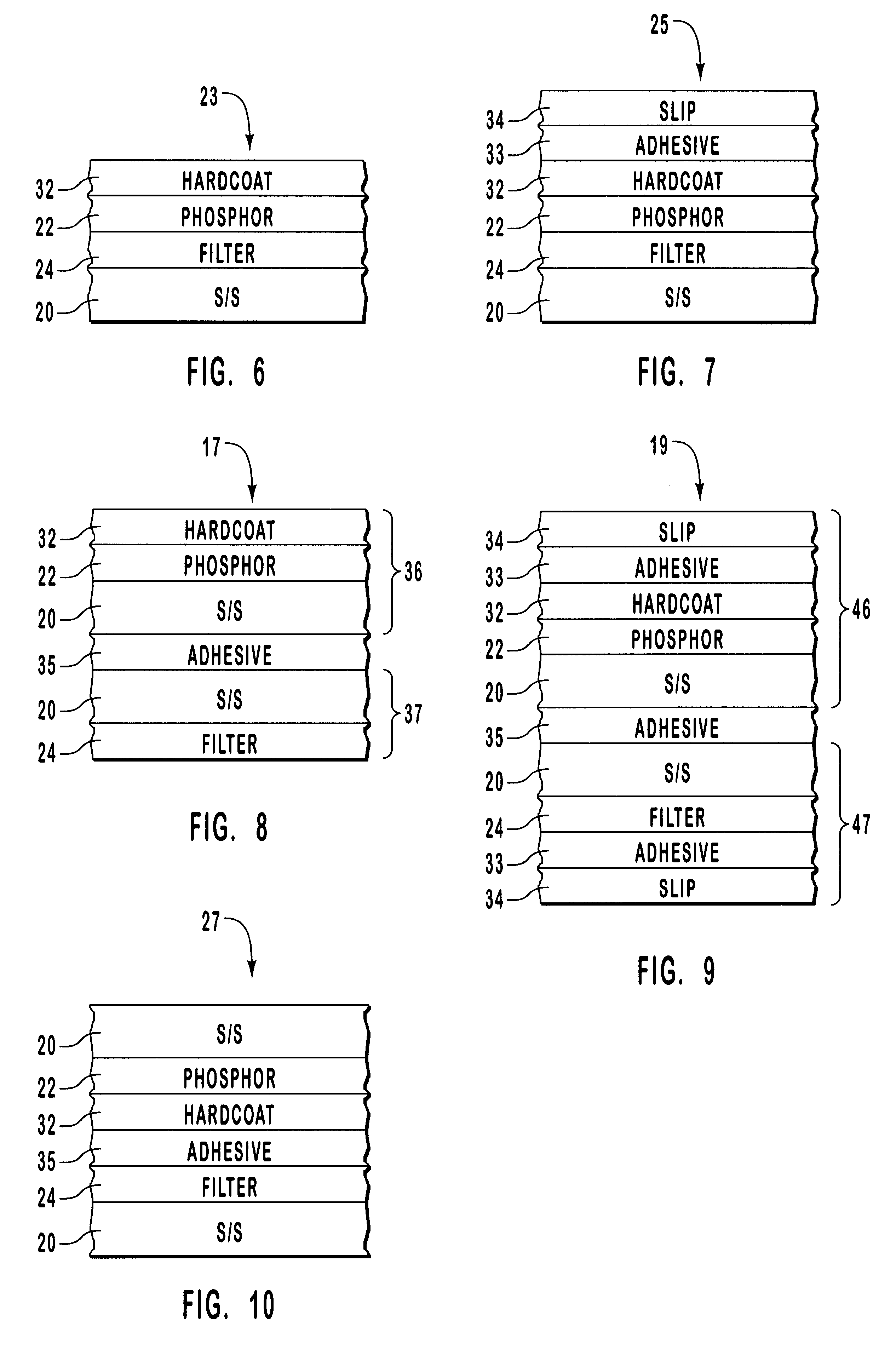
FIG. 10 depicts yet another of the possible two-substrate embodiments, an embodiment 27 in which the two substrates provide outer protection and the fluorescent layer may be protected internally by an optional hardcoat layer 32. The overall structure is: substrate#1 / phosphor / optional hardcoat / adhesive / filter / substrate #2.
Exemplary Reference Cards
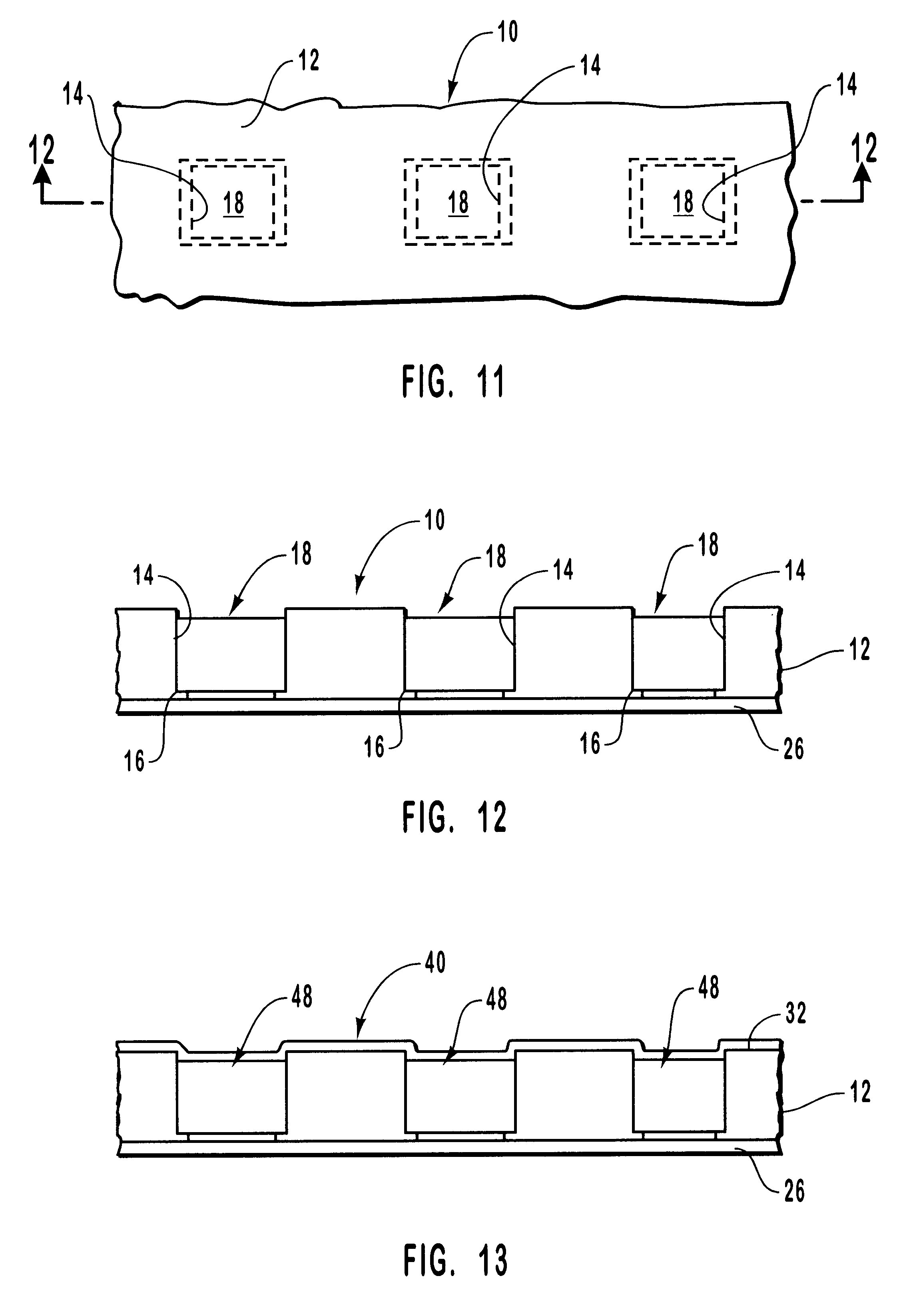
FIGS. 11 and 12 are, respectively, a simplified top plan view and a longitudinal vertical section view, expanded vertically for ease of understanding, of an exemplary solid fluorescence material, emission-attenuated reference card 10 in accordance with the present invention. The basic card itself is well known in the relevant technology, and comprises preferably a support or base or substrate 12, of material such as glass or plastic, having so-called "wells" (optically transparent regions or physical holes) 14 extending from one major surface to the other, illustratively from the top to the bottom surface. (As used here, "optically transpare...
examples
Dielectric filters controlling light in the UV, visible, and / or IR region were formed by standard vacuum coating techniques. The filters were designed to pass maximum light intensity in the excitation band of a phosphor material, but to transmit only a controlled amount of the emitted (fluorescent) light. Specifically, for Eu.sup.+2 -doped phosphor, the filter was designed for maximum transmittance at 365 nm, but only limited transmittance at 450 nm, near the fluorescence maximum. Separate filters were then designed to transmit discrete amounts of the fluorescence intensity, such as 10%, 5%, 1%, 0.3%, etc. Filters and phosphor were applied to a range of transmitting base or substrates including common glass, colored glass, fused silica, etc.
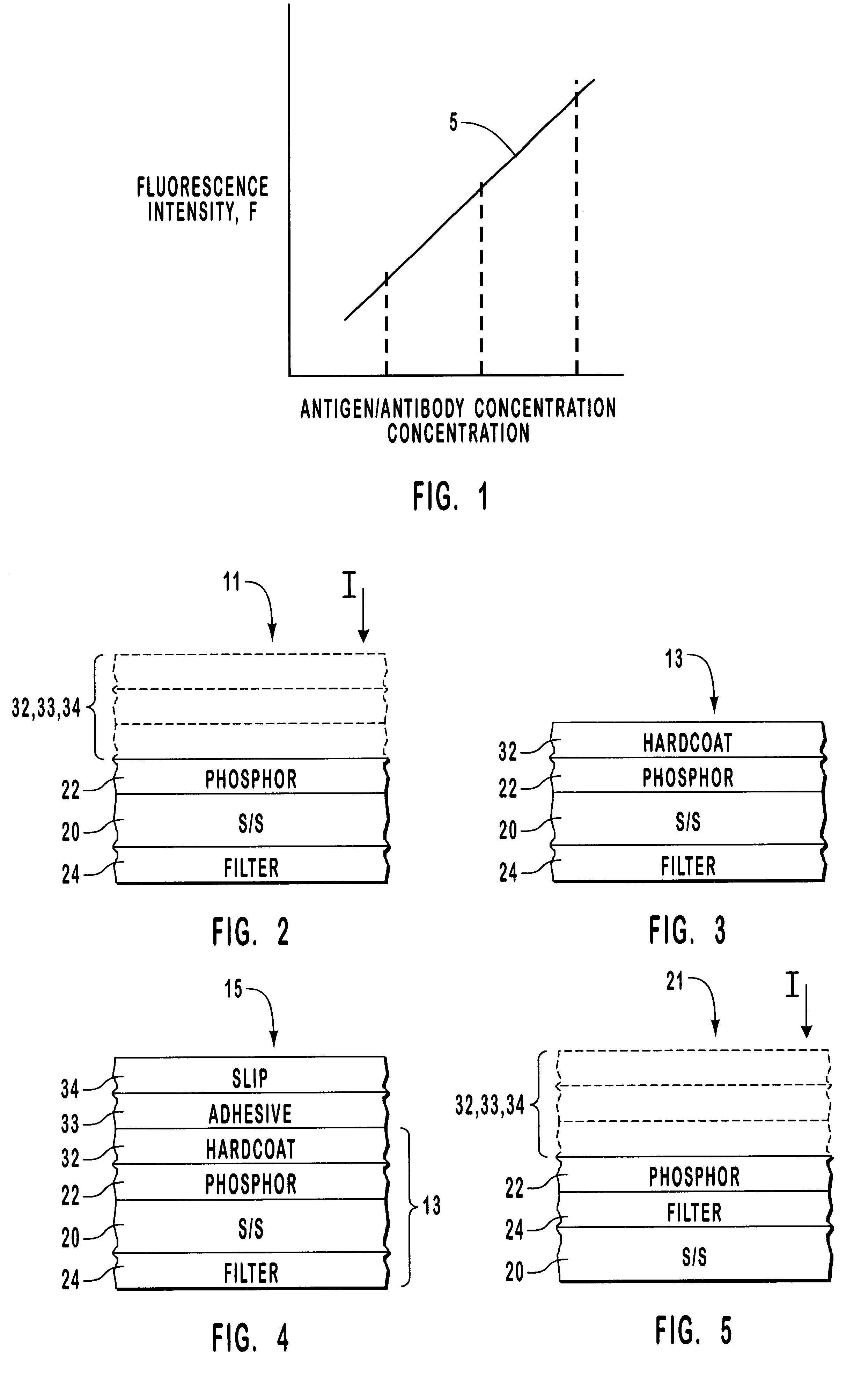
In specific examples, discrete reference devices 18 having the structure 15, FIG. 4, were formed having the following construction / characteristics:
slip / adhesive / hardcoat / phosphor / substrate / filter #1;
slip / adhesive / hardcoat / phosphor / substrate / filte...
PUM
| Property | Measurement | Unit |
|---|---|---|
| Adhesivity | aaaaa | aaaaa |
| Wavelength | aaaaa | aaaaa |
| Fluorescence | aaaaa | aaaaa |
Abstract
Description
Claims
Application Information