The
distortion effects of permeable metals are not addressed by this system.
This means that
steel structures in, around, and under the operating region of the system will distort the received magnetic fields and degrade system performance.
This is unacceptably slow for many applications.
This system has no provision for reducing the effect of nearby permeable metals, nor does it address the drawback of requiring a slow update rate while operating near large, thick sheets of highly conductive metals.
Large sheets of
metal, however, can have an effective loop area larger than the magnetic transmitter loops, which diminishes this
advantage in field fall
off rate, which has the general effect of making the system quite sensitive to large metallic objects.
Also, metallic objects parallel to and near the transmitter loops produce very large
eddy current magnitudes which reduces the
signal level within the operating volume.
As these differences become small, a small change on one of the vectors can result in a large apparent change of
receiver position.
One
disadvantage of this system is its bulk, requiring the operating volume to be surrounded by the "Helmholtz" coil
assembly.
A second
disadvantage of this system is that, when placed upon a
metallic object such as a steel table, the magnetic field from the transmit coils will be distorted inside of the operating volume.
The
dipole transmitter in this system must be located over the center of the spiral
ground plane assembly, which makes patient placement more difficult in a clinical setting, as this placement may interfere with the surgical field during certain procedures.
The benefit of this method is that it is possible to locate the transmitter closer to the
ground plane, and one does not need to use the "
method of images" to solve for position, but the
disadvantage of transmitter location over the spiral /
ground plane assembly is very similar to the case of a ground plane only.
The system does not determine position, and does not utilize any methods for reducing the effect of nearby metallic objects.
(1) In the preferred embodiment, a flux containment means is used to re-direct the flux vectors such that they are enhanced inside of the sensor operating volume and decreased under and adjacent to the transmitter plane, which reduces the sensitivity of the system to metals under and near the transmitter. The flux vectors from the transmitters are distorted by the flux containment means in a stable and repeatable manner, thus it is possible to precisely and repeatably characterize the distorted field. Once the precise
vector distribution from the transmitter assembly is known, solution of position and orientation from a receiving means is a straightforward task to those familiar with the magnetic
position tracking art. One reliable method for accomplishing this vector characterization is to utilize finite
element analysis to compute the magnetic field vectors from the transmitter. Another reliable method is to employ one of several so-called
mapping techniques which are known processes to those familiar with the art.
(2) The preferred embodiment of the present invention teaches a method for creating a representative magnetic transmitter assembly with reduced sensitivity to metallic objects under and adjacent to the operating volume of the system. The preferred embodiment also reduces the vector
dilution effects of a conductive ground plane to levels which are no longer of concern. This reduction in vector
dilution yields a system which is substantially less sensitive to
distortion caused by metallic objects within the operating volume while maintaining insensitivity to metallic objects below the transmitter and reduced sensitivity to objects adjacent to the operating volume. The transmit means may include wire loops, solenoids, or permanent magnets arranged in convenient shapes and locations for determining the position of the
receiver within the volume.
(3) The present invention achieves the requirement for a system which may be placed upon a surface of any extent and composition without degrading the accuracy of the position readings from a sensor located within the desired operating volume. It achieves this goal for both AC and DC transmitter excitations, which is not at all possible using prior art ground plane based
compensation methods. It achieves this goal while significantly increasing the magnetic
field intensity within the operating volume, which is not possible using prior art ground plane based
compensation methods. It also avoids the problem of vector
dilution which is introduced when a conductive ground plane is placed near the transmitter.
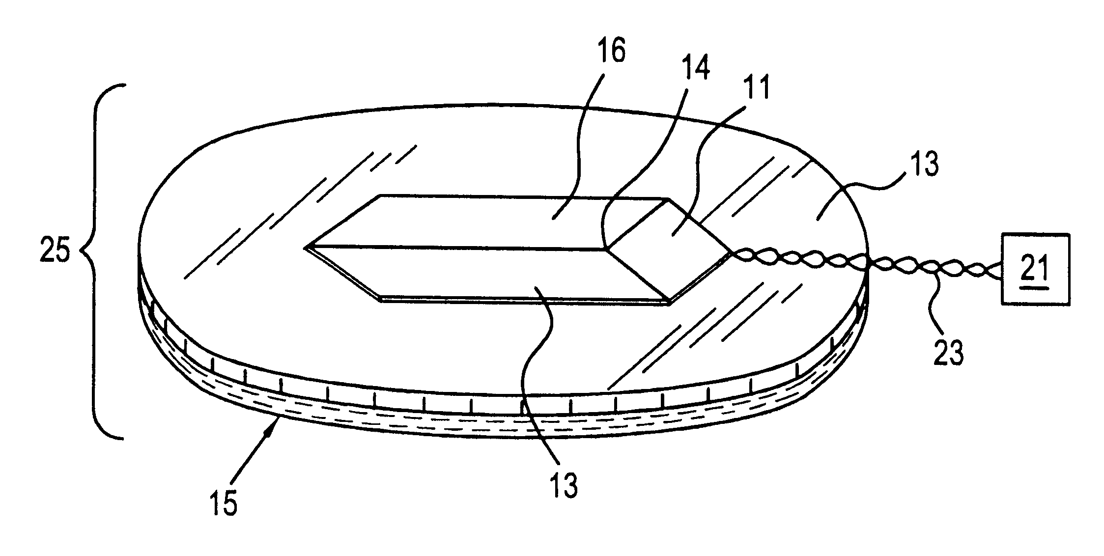
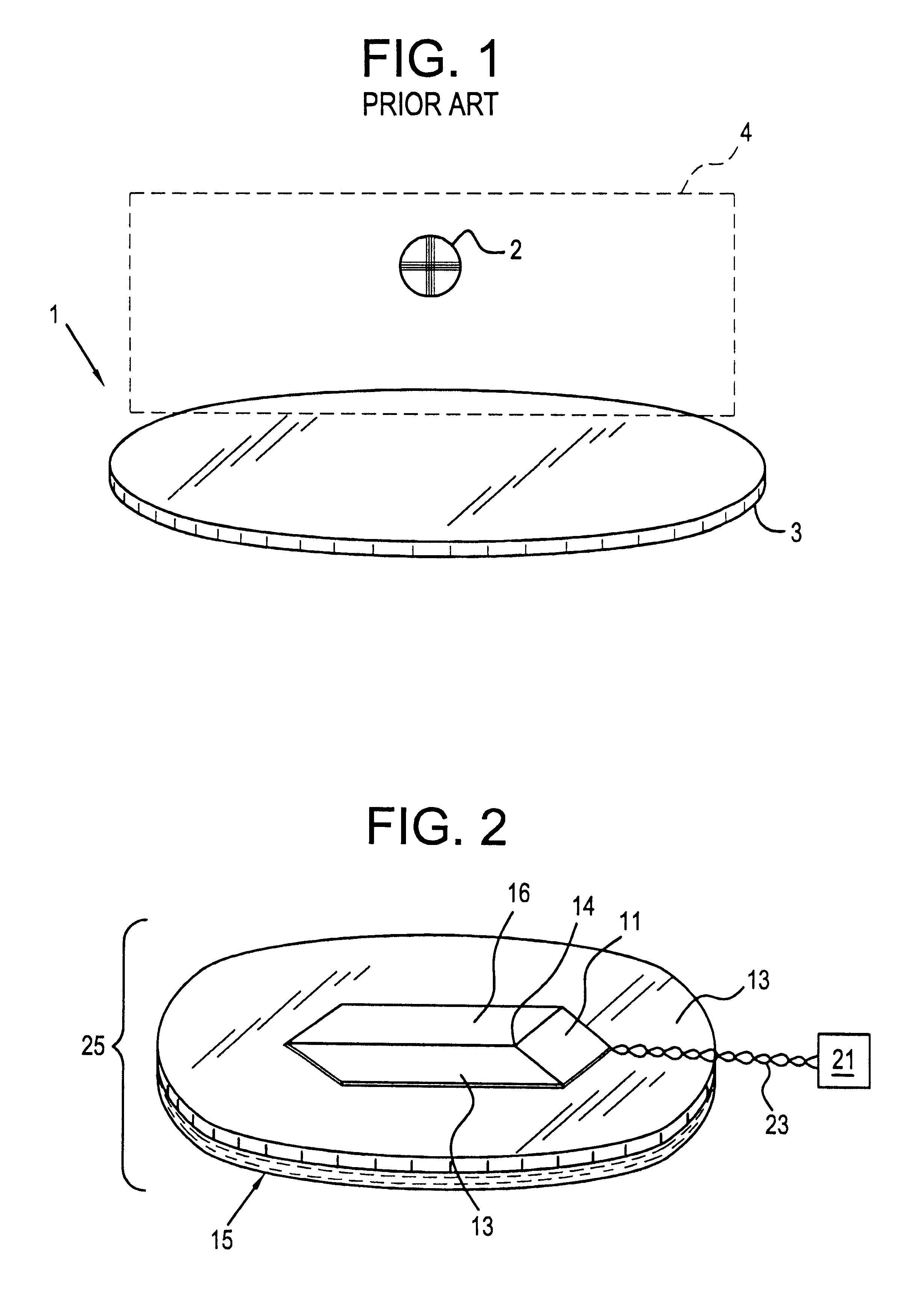
(4) In the preferred embodiment of the present invention, a thin, permeable barrier made of a highly permeable but substantially non-conductive material such as ferrite or mumetal is placed on top of a conductive plate. In the preferred embodiment, the thickness of the permeable layer when made of ferrite is from 0.05 inches to 0.25 inches whereas use of mumetal can reduce the thickness to below 0.01 inches. The conductive plate, preferably made of an aluminum
alloy, may be from 3 / 16 of an inch to 1 / 4 inch in thickness. Where mumetal is employed in the permeable layer, the thickness of the conductive plate may be reduced because the thickness is not chosen for mechanical support. On top of the ferrite or mumetal barrier, a planar rhombic three axis transmitter is placed, details of which are presented in U.S. Pat. 5,600,330. In the preferred embodiment, the transmitter consists of a PC board with the transmitter etched thereon. PC boards having thicknesses varying from 0.03125-0.125 inches may be employed.
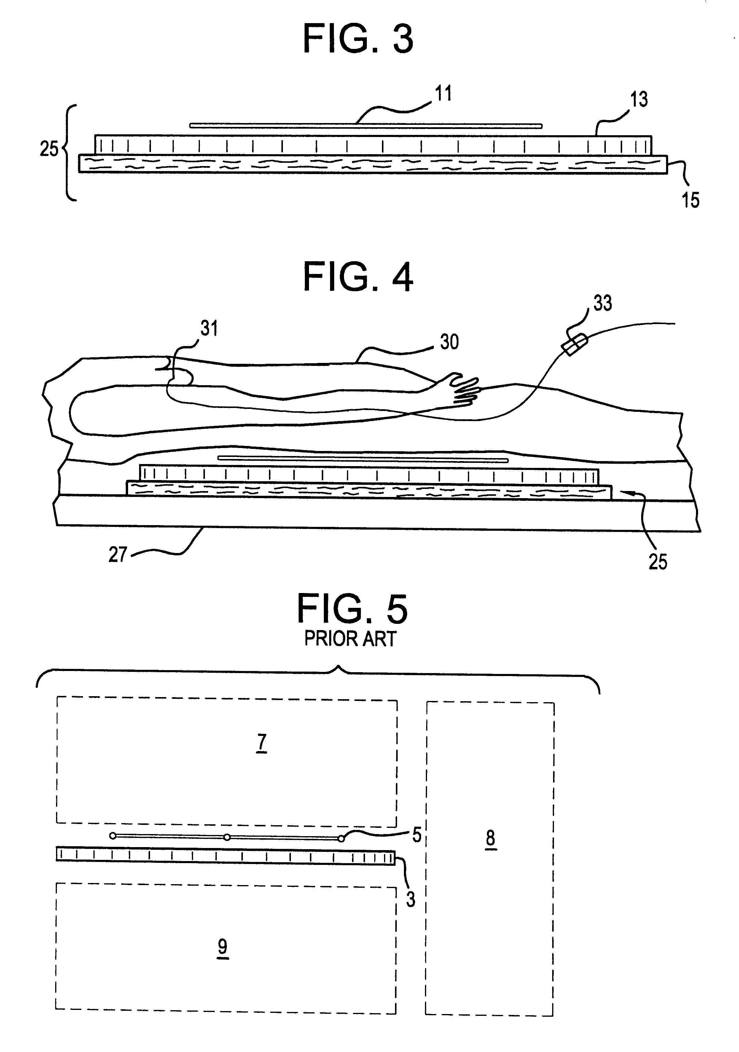
(5) If desired, the permeable barrier may have a flat, planar configuration. Alternatively, it may be made to resemble, in cross-section, a cake pan having a flat
central region with uplifted
peripheral edges. Alternatively, the permeable barrier may have a generally flat configuration with peripheral edges that taper outwardly from the top surface thereof to the bottom surface thereof with the taper making an angle with the bottom surface in the range of, preferably, 3.degree. to 85.degree..
(6) If a conductive object in the regions adjacent to or under the transmitter is subjected to an AC magnetic field, an
eddy current will be induced in the object. This induced eddy current will produce a magnetic field component, which, by the addition of vectors, will combine with and distort the normal
metal-free magnetic field near the object. The magnitude of this parasitic eddy field is proportional to the magnitude of the
AC field near the conductive object.
(7) It is thus seen that if the field vectors in the operating volume above the transmitter assembly remain constant in magnitude and direction while the field magnitude in the regions adjacent to and under the transmitter assembly are reduced, then metallic objects in those regions will have a proportionally reduced distorting effect on the field in the operating volume above the transmitter assembly. If the field magnitude in the operating volume above the transmitter assembly is increased while the field magnitudes in the regions adjacent to and under the transmitter assembly remain constant, the distortion reducing effect is similar. Accordingly, the ratio of the
magnetic field amplitude in the operating region above the transmitter assembly over that of the regions adjacent to and under the transmitter assembly may be used to predict sensitivity to metallic objects. A similar description applies to ferromagnetic distortion effects when the distorting objects are located in the regions adjacent to and below the transmitter assembly.
(8) If the relative magnetic distortion sensitivity values of a single transmit coil in the configuration such as is shown in FIG. 13, can be established as a normal value, then a relative distortion sensitivity
figure of merit Ma for objects adjacent to the operating volume may be defined where Ma equals (the field of the system depicted in FIG. 2 in the region above the transmitter assembly) divided by (the field of the system depicted in FIG. 5 in the region above the transmitter assembly) divided by (the field of the system illustrated in FIG. 2 in the region adjacent the transmitter assembly) divided by (the field of the system in the configuration of FIG. 5 in the region adjacent the transmitter assembly). The system depicted in FIG. 11 will have a sensitivity
figure of merit of 1 in that FIG. 11 will, for example, be chosen as the reference system.
(9) Similarly, for comparison of objects below the transmitter assembly, we can define a term Mb which equals (the field of the system of FIG. 2 in the region above the transmitter assembly) divided by (the field of the system illustrated in FIG. 5 in the region above the transmitter assembly) divided by (the field of the system of FIG. 2 below the transmitter assembly) divided by (the field of the system of FIG. 5 in the region below the transmitter assembly). Using the figures of merit Ma and Mb, several different configurations can be evaluated to determine likely relative sensitivities to metallic objects in the regions adjacent to and below the transmitter assembly.

