
Magnetic azimuth measuring system based on giant magneto-resistance sensor, measurement method and perpendicular compensation method

A giant magnetoresistive sensor and geomagnetic azimuth technology, which is applied in measuring devices, instruments, surveying and navigation, etc., can solve problems such as low resolution, poor dynamic performance, and complex structure of geomagnetic sensitive components

Inactive Publication Date: 2012-01-11
SHANGHAI UNIV
View PDF6 Cites 33 Cited by
  • Summary
  • Abstract
  • Description
  • Claims
  • Application Information

AI Technical Summary

Problems solved by technology

In the fluxgate compass, the fluxgate sensor mostly adopts a dual-axis measurement method, and the inclinometer used inside has a complex structure, limited accuracy, and poor dynamic performance, which is not suitable for fast-moving objects
[0005] 2) Magnetoresistive compass, using magnetoresistive sensor as the measuring element, no rotating parts, small size and good dynamic performance, but the magnetoresistance effect of commonly used magnetoresistive elements is only 2% to 3%, the resolution is not high enough, in geomagnetic measurement It shows that the measurement accuracy is limited, and it is impossible to achieve high-precision geomagnetic measurement
[0006] Among the above-mentioned geomagnetic sensors, the geomagnetic sensitive elements have complex structures, low resolution, and poor dynamic performance. If there are errors in the measurement of the attitude data roll angle and pitch angle of the equipment in the geomagnetic detection, it will bring great difficulties to the determination of the azimuth angle. Large error, reduce equipment accuracy

Method used


Image

  • Magnetic azimuth measuring system based on giant magneto-resistance sensor, measurement method and perpendicular compensation method
  • Magnetic azimuth measuring system based on giant magneto-resistance sensor, measurement method and perpendicular compensation method
  • Magnetic azimuth measuring system based on giant magneto-resistance sensor, measurement method and perpendicular compensation method

Examples


Embodiment 1

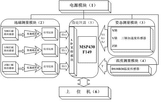
[0044] see figure 1 , the geomagnetic azimuth measurement system based on the giant magnetoresistive sensor consists of a power module (1), a geomagnetic measurement module (2), an attitude measurement module (3), a temperature measurement module (4), a microprocessor (5) and a host computer (6) Composition. The power supply module (1) provides a stable 3.3V power supply for the system; the geomagnetic measurement module (2) includes X-axis, Y-axis and Z-axis giant magnetoresistive sensors and corresponding signal processing circuits on each axis; the attitude measurement The module (3) includes X, Y, Z three-axis acceleration sensors orthogonal to each other; the geomagnetic measurement module (2) is connected to the A / D sampling port of the microprocessor (5); the attitude measurement module (3) and The temperature measurement modules (4) are respectively connected to the digital IO ports of the microprocessor (5); the microprocessor (5) is connected to the host computer (6...

Embodiment 2

[0046] This embodiment is basically the same as Embodiment 1, and the special features are: the power supply module (1) uses a voltage conversion chip 1117; the geomagnetic measurement module (2) uses a three-axis giant magnetoresistive sensor AAH002-02 connected to an RC low-pass Filtering circuit and instrumentation operational amplifier INA118; the attitude measurement module (3) uses a three-axis acceleration sensor ADXL345; the temperature measurement module (4) uses a temperature sensor DSB18B20; the microprocessor (5) uses a microprocessor MSP430F149 , after preprocessing the geomagnetic information, pitch information and temperature information, the geomagnetic azimuth is obtained after processing by the host computer (6).

Embodiment 3

[0048] This measurement method of geomagnetic azimuth based on the giant magnetoresistive sensor adopts the above-mentioned measurement system.

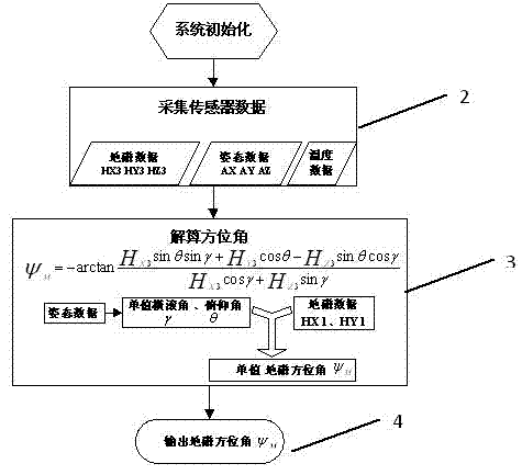
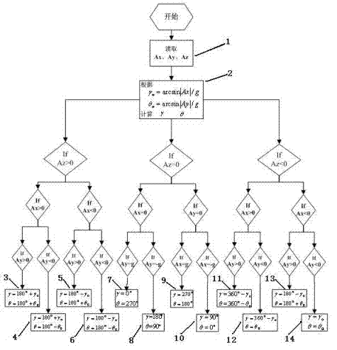
[0049] The geomagnetic azimuth measurement process is as follows: figure 2 as shown, image 3 against figure 2 In step 3 of the azimuth angle calculation, the single value realization process of roll angle and pitch angle is described in detail, Figure 4 against figure 2 The single-valued realization process of the azimuth angle in step 3 of the azimuth angle calculation is described in detail. The specific steps of geomagnetic azimuth measurement in this system are as follows:

[0050] (1) if figure 2 Process 1 system initialization;

[0051] (2) if figure 2 Process 2 collects sensor data. Includes: Geomagnetic Data , attitude data Ax, Ay, Az, temperature data T;

[0052] (3) if figure 2 Process 3 calculates the geomagnetic azimuth, including:

[0053] Such as image 3 Obtain the unique pitch angle of a single...


PUM


Abstract

The invention discloses a magnetic azimuth measuring system based on a giant magneto-resistance sensor, a measuring method and a perpendicular compensation method so as to realize omnibearing measurement of a magnetic azimuth and reduce measurement error caused by non-orthogonal and zero deviation of a three-axis sensor. The measuring system comprises an earth three-axis magnetic measurement module, a three-axis attitude measurement module, a temperature measurement module, a microprocessor and an upper computer. The invention relates to the technical field of intelligent sensor technologies,digital signal processing and the like. The invention provides an intelligent octant judgment method based on a three-axis acceleration sensor against the multi-valued problem of azimuth measurement caused by a mathematical model when the giant magneto-resistance sensor is used for performing the azimuth measurement so as to realize the omnibearing angle measurement based on the giant magneto-resistance sensor. Simultaneously, the invention provides a three-axis orthogonal and zero compensation method which is completed in the microprocessor against the measurement error caused by the three-axis non-orthogonal and zero deviation of the giant magneto-resistance sensor so as to improve the measurement precision of the measuring system. In addition, the invention further has the characteristics of low development cost, simple hardware circuit and the like.

Description

technical field [0001] The invention relates to a geomagnetic azimuth measurement system based on a giant magnetoresistance sensor and a three-axis acceleration sensor, and a method for realizing an all-round measurement of the geomagnetic azimuth, in particular to a microprocessor-based three-axis positive measurement system for a giant magnetoresistance sensor. Intersection and zero compensation method. It belongs to the field of digital signal processing and intelligent sensor technology. Background technique [0002] With the continuous development of human beings, in the fields of modern aviation, aerospace, navigation, geological exploration, marine survey and other fields, orientation technology is indispensable, and azimuth measurement technology is becoming more and more important. Common azimuth measurement methods at this stage include: gyroscope, radio heading instrument, GPS and magnetic heading sensor. Gyroscopes have high accuracy and good stability, but the...

Claims


Application Information

Patent Timeline
IPC IPC(8): G01C17/30G01C17/38
Inventor 付敬奇郑学理
Owner SHANGHAI UNIV
Learn More