
Infra red filter

Inactive Publication Date: 2001-06-26
THALES OPTRONICS TAUNTON +2
View PDF15 Cites 19 Cited by
  • Summary
  • Abstract
  • Description
  • Claims
  • Application Information

AI Technical Summary

Benefits of technology

It is evident from the above that the problem of finding a material which can be toughened to make it suitable in particular for aviation use, which is able to reduce IR transmission to a satisfactory level yet not eliminate it entirely, which does not result in adverse color shifts in the visible range, and which is capable of being formed to make lenses remains to be solved.
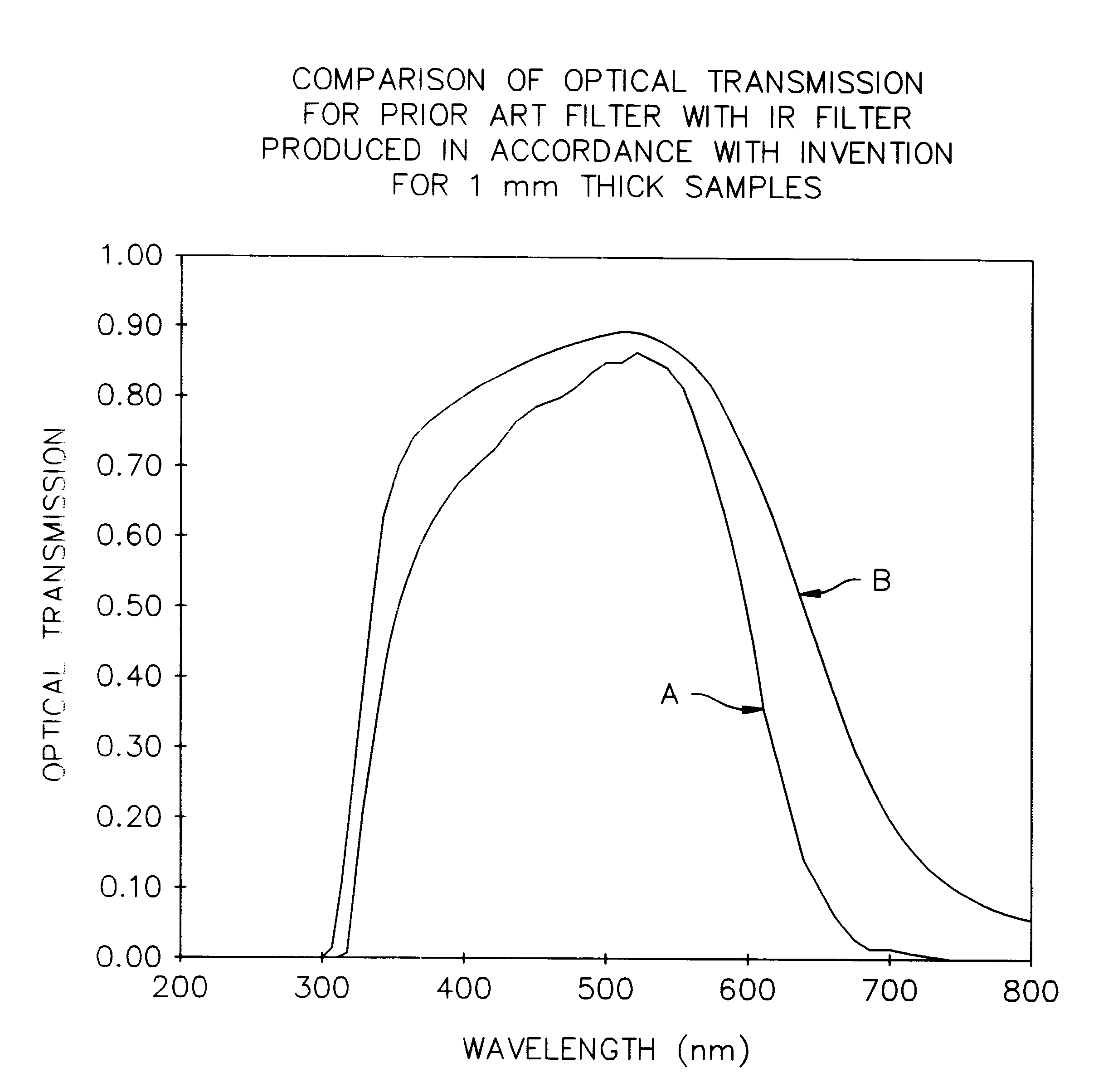
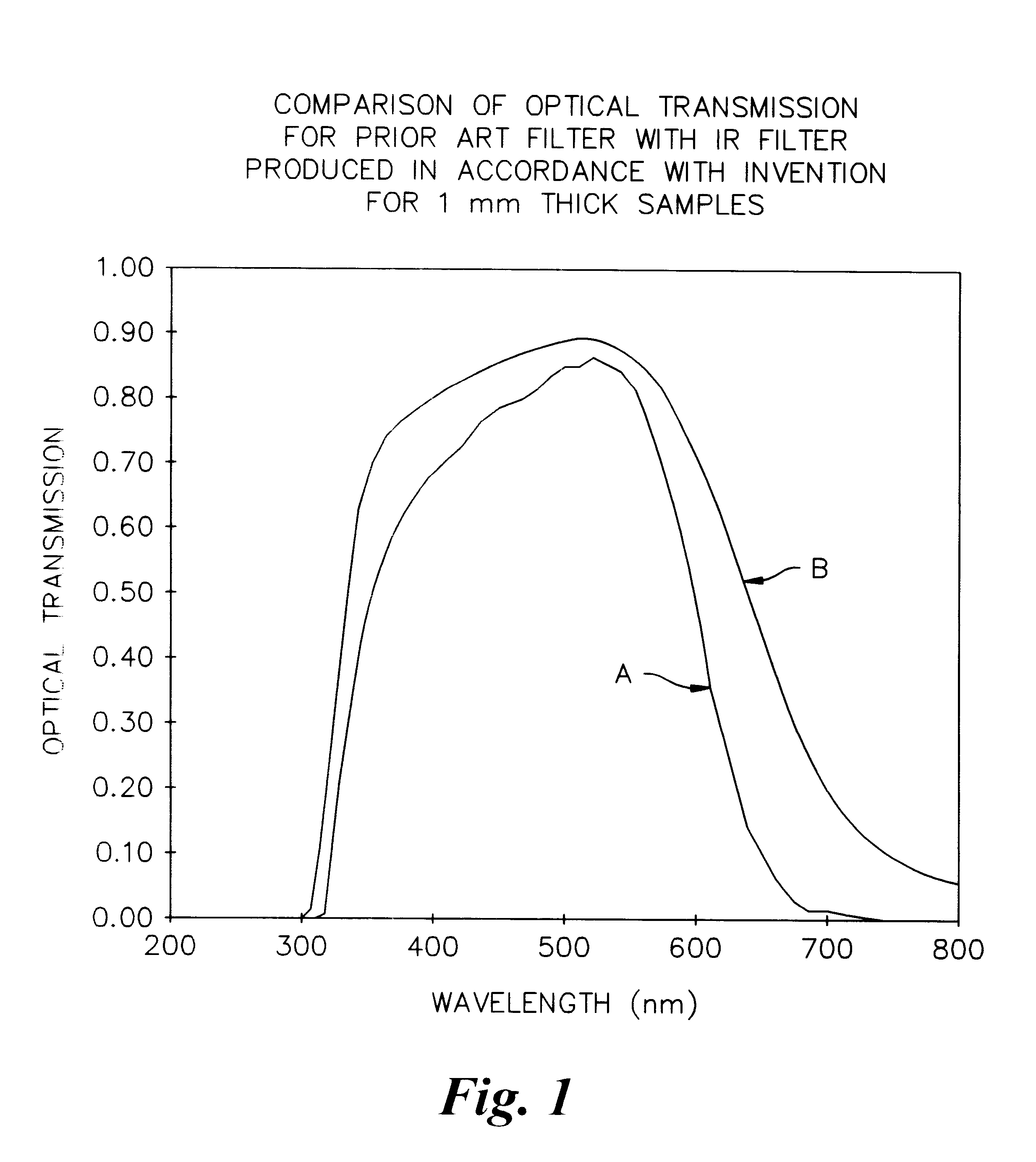
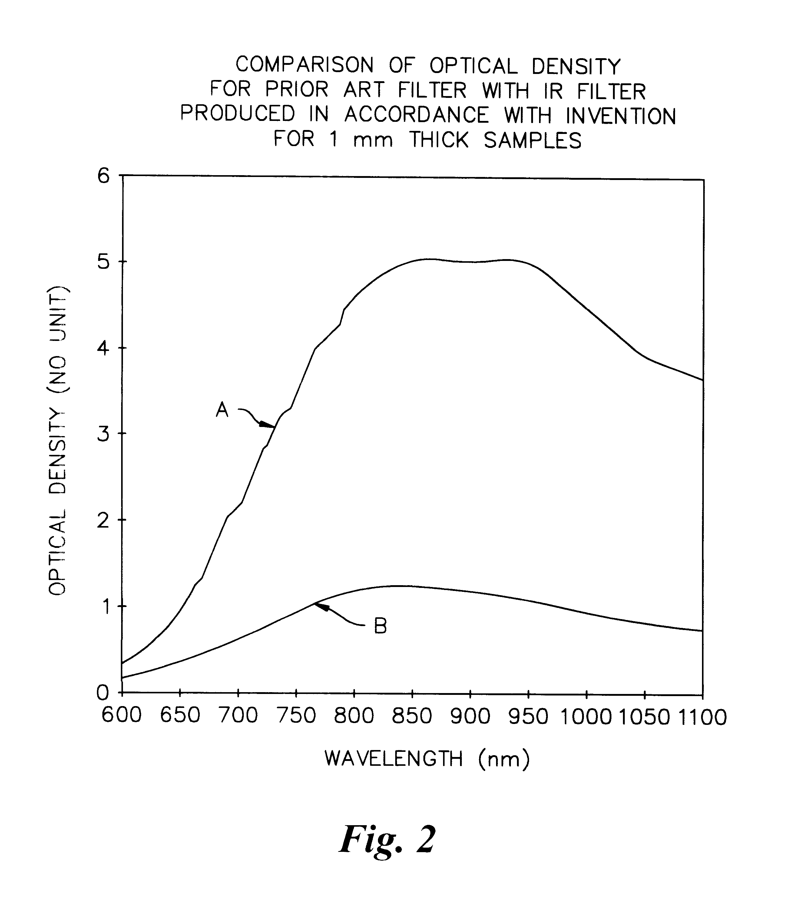
However, by means of this invention, it is possible to attenuate the IR radiation to a level which does not have an adverse effect on the automatic gain control of the pilot's goggles yet allows the pilot to readily identify the light source. Moreover, the glass composition has little or no appreciable effect on the visible spectrum.
It will be appreciated that by means of this invention, we have made a major contribution to improving air safety in poor visibility conditions.
Apart from this significant contribution to safety, our research in this area has resulted in another important advance in phosphate glass technology. In particular, we have found that it is possible to form or bend phosphate glass without causing cracking or affecting the long term stability of the glass. Furthermore, when the process of forming is applied to the IR filter glass of the invention it has no deleterious affect on the optical properties of the glass.
Also, ceramic has a lower thermal conductivity than the traditionally used cast iron so that it does not chill the glass surface when the glass and mold are in contact. In this way, deterioration in surface quality and cracking can be successfully avoided. Another reason for choosing ceramic over cast iron is that cast iron oxidizes readily at the forming temperatures involved thus further reducing surface quality of the glass.
The composition of the glass according to the invention and the method for forming the same have together made it possible to form intricate shapes. In particular, because the phosphate glass of the invention is chemically more stable when heated than previously available glass and the method used to form the glass minimizes the extent to which it is exposed to high temperatures.

Problems solved by technology

While the automatic gain control operates satisfactorily in most conditions, it is unable to compensate when a very bright light is introduced into the field of view.
Such a situation occurs, for example, when the pilot approaches another aircraft at night and results in the output image becoming very bright and occasionally the whole display is "bleached".
The inability of the goggles to cope with bright lights at night can therefore make it difficult for the pilot accurately to locate other aircraft in the vicinity and, at worst, may temporarily blind the pilot.
In such circumstances, it will be appreciated that both aircraft can be placed in an extremely dangerous situation.
Although IR filter glass of the silicate type is commercially available, it is of limited use for aircraft lights because the light emitted in the visible spectrum is also affected.
In this regard, it produces a measurable color shift in the red region making it difficult to comply with the CAA regulations.
The high temperatures involved in forming the glass sections for subsequent assembly into the lens means that such coatings can only be effectively applied after the forming stage.
However, coating with an IR filter material after assembly of the lens has still proved unreliable because of the highly contoured surfaces involved.
In particular, it has been difficult to coat either the interior or exterior surfaces of the lenses uniformly.
In order to be effective, IR filter coatings must be evenly applied; too thin a coating will result in inadequate IR attenuation with potentially disastrous consequences and too thick a coating may block out the IR spectrum completely.
Coating of lenses made from conventional silicate glass is therefore problematic.
However, for external lighting applications the glass would need to be only 1 mm thick, rendering it useless mechanically; in particular, because of its inability to withstand the treatment involved in known glass toughening processes.
Moreover, in its known applications phosphate glass is characterized by its brittle nature and hence it has not hitherto been possible to form into substantially non-planar components.

Method used


Image

  • Infra red filter
  • Infra red filter
  • Infra red filter

Examples


example 4

A piece of copper doped phosphate glass of approximate dimensions 100 mm.times.50 mm.times.4 mm thick was machined from the raw sheet of 10 mm thick by reducing the thickness equally on each face. The piece was then profiled on its edges to the pre-slump shape. The glass was subsequently placed on the ceramic mold in a furnace and the temperature raised from ambient to 550.degree. C. at a rate of 100.degree. C. / hour. This temperature was maintained for 30 minutes by which time the glass had formed itself to the shape of the mold. The temperature was then allowed to fall to 500.degree. C. over a period of 30 minutes and held at this temperature for 2 hours at which stage the glass was then removed from the mold inside the furnace. The furnace temperature was then reduced to 300.degree. C. over a period of 2 hours and then held at 300.degree. C. for 3 hours. After this intermediate stage, the furnace temperature was again reduced to ambient (25.degree. C.) over a period of 8 hours. Th...


PUM

PropertyMeasurementUnit
Lengthaaaaaaaaaa
Lengthaaaaaaaaaa
Lengthaaaaaaaaaa

Abstract

A phosphate glass doped with copper in an amount of less than 2% by weight is formed to produce a lens for use on external aircraft lights. The glass attenuates infra red radiation to a degree where it does not pose a danger of temporarily blinding a pilot wearing night vision goggles yet remains visible. The glass has little appreciable effect on light transmission in the visible spectrum. Conveniently, the glass can be formed by slumping at a softening temperature against a mold to produce intricate lens shapes. In addition, the glass is able to withstand conventional toughening processes.

Description

BACKGROUND OF THE INVENTIONThe present invention relates to a phosphate glass for use as an infra red (IR) filter and to a method of forming the same, and is particularly but not exclusively directed towards filters for use on external lights for aircraft, ships and the like.Aircraft lights, whether fitted to civil or military aircraft, generally comprise navigation lights at the wingtips (red port and green starboard) and white tail lights. High intensity anti-collision strobe lights are also fitted at the top and bottom of the fuselage.Strict regulations operate to govern the color and intensity of aircraft lights. In the United Kingdom, the Civil Aviation Authority ("CAA") has responsibility for ensuring that all aircraft adhere to the regulations. For example, at least in relation to civil aircraft, the red and green wingtip lights must fall within stipulated color bandwidths, so that an aircraft whose lights emit an orange or a blue hue, rather than red or green, would fail to ...

Claims


Application Information

Patent Timeline
IPC IPC(8): C03C3/17C03C3/12C03C3/062G02B5/22C03C3/16C03B25/04
CPCC03C3/062C03C3/17G02B5/22
Inventor COOK, TREVORSAUNDERS, ADRIAN
Owner THALES OPTRONICS TAUNTON
Learn More