Apparatus for manufacture of a plastic bag with standup bottom wall

a technology of plastic bags and bottom walls, which is applied in the field of apparatus for manufacturing plastic bags with stand-up bottom walls, can solve the problems of high cost of bags, complex manufacturing of plastic bags in the prior art, and inability to generally provide plastic bags which will stand up. to achieve the effect of cost-effectiveness

Inactive Publication Date: 2001-07-03
HUDSON-SHARP MACHINE COMPANY
View PDF15 Cites 25 Cited by
  • Summary
  • Abstract
  • Description
  • Claims
  • Application Information

AI Technical Summary

Benefits of technology

The preferred bag making machine is a high speed bag making machine employing an apparatus which is specially constructed or modified and joined into a bag making machine to form stacks of individual flat bags with the special creased bottom patterns to readily produce a stand up bag unit with an essentiall

Problems solved by technology

Plastic bags which will stand have not generally been available, particularly at a competitive cost.
Generally, the prior art plastic bag is considered complex to manufacture and still

Method used


Image

  • Apparatus for manufacture of a plastic bag with standup bottom wall
  • Apparatus for manufacture of a plastic bag with standup bottom wall
  • Apparatus for manufacture of a plastic bag with standup bottom wall

Examples


Embodiment Construction

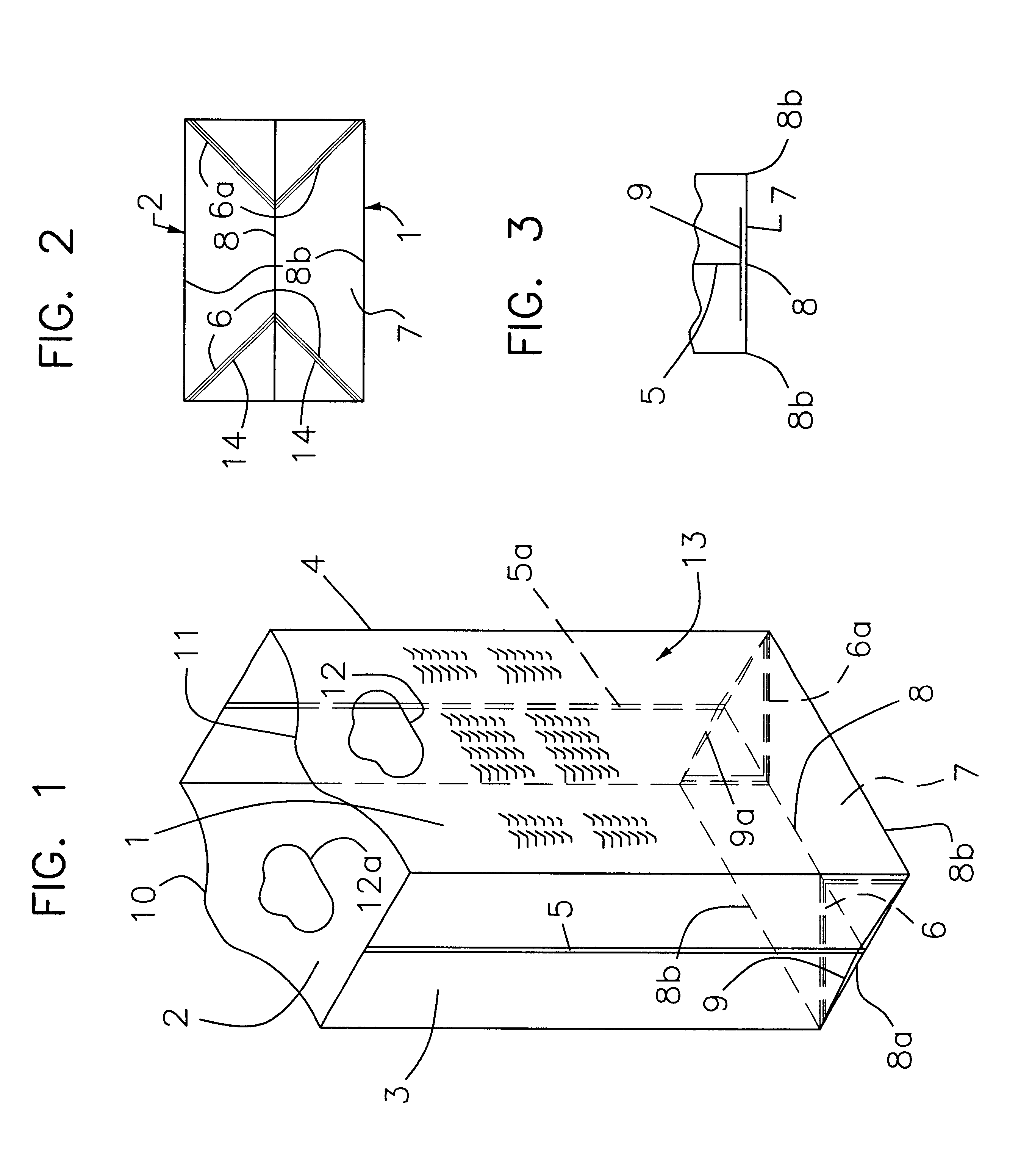
Referring to the drawings and particularly to FIG. 1, an open plastic bag is illustrated incorporating an embodiment of the present invention.

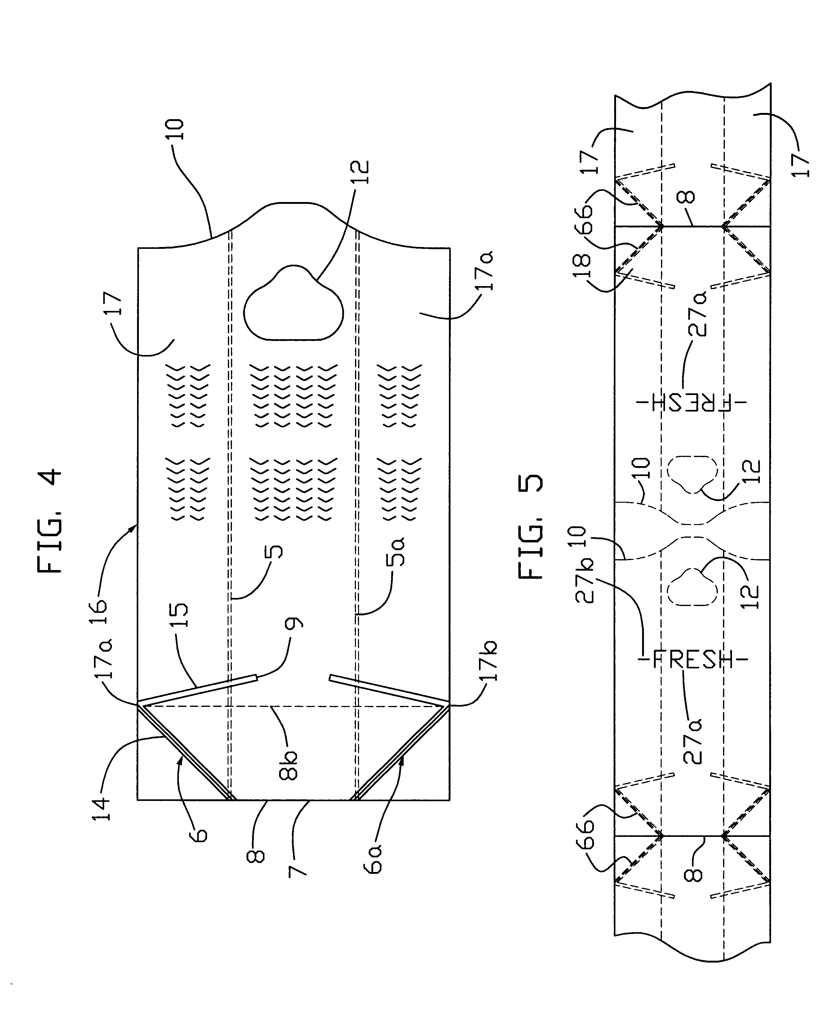
The plastic bag is preferably formed of clear or semi-clear polyethylene plastic and may include various printed information thereon. The bag is formed of a relatively thin plastic with the thickness varying with the application, as previously discussed and disclosed. The illustrated bag is typically a rectangular shaped bag having front and back panels 1 and 2 connected by integral side walls or panels 3 and 4. The panels are shown all generally rectangular. The bag as shown is formed from a multi-layered web segment consisting of a pair of like-abutting layers of plastic film. The illustrated bag is particularly formed from a tubular plastic film, as hereinafter described.

The side panels 3 and 4 are formed as extensions of the front and back panels 1 and 2 and may be joined at the center by seams 5 and 5a. The seams 5 and 5a are specially ma...


PUM

PropertyMeasurementUnit
Angleaaaaaaaaaa
Angleaaaaaaaaaa
Widthaaaaaaaaaa

Abstract

A flat plastic bag is formed from a side gusseted tubular web. The bag is formed with an open end and a opposite spaced end seal. Hinge crease patterns are formed in each of the gusseted portions at the bottom end of the bag. The pattern includes a two ridge upper leg and a three ridge bottom leg which are formed by a cold sealing process. A bag making machine includes a web supply which is passed through a web feed supply section to form the gusseted web. The gusseted web is sent through a forming section. The segment is first formed with the patterns of two bags in immediately adjacent relationship and located to the opposite sides of a common line defining the end of the adjacent bags. The web is formed into two bag segments with the creases located at each of the segment ends. The web is passed through a unit creating the seal and simultaneously severing the upstream segment. The segments are stacked on a table with each stack sequentially transferred to a punch unit which severs the center portion of the segment to define open bag ends adjacent each other with interconnections to maintain the stack relationship between the separated bags. The formed stack is passed through a separation unit which removes the cut portions thereby separating the bags for transport to a conveyor. The bag may be formed with ventilation openings at the punch unit. The crease pattern with the bottom portion includes a plurality of creases to ensure the proper location of at least one crease within the gusseted portion to ensure easy opening of the plastic bag.

Description

The present invention relates to a method and apparatus for the manufacture of plastic storage containers and particularly folded flat plastic bags with an integrated formed standup bottom wall structure to provide a stand up plastic bag.Common plastic bags are widely used in the packaging of products at the point of sale. The weight of the plastic and the construction will vary somewhat with the particular application, and particularly dependent upon the required strength of the bag. Such bags are used as an alternative to paper bags which are also folded members and specially formed with a bottom structure which, when the bag is opened, permits the direct standing of the paper bag to receive the product.Plastic bags which will stand have not generally been available, particularly at a competitive cost. The assignee of this application is an owner of various pending patent applications disclosing a plastic bag construction which permits a folded flat plastic bag to be opened and wi...

Claims


Application Information

Patent Timeline
IPC IPC(8): B31B1/25B31B1/00B31B37/00B65D33/01B65D30/18B65D30/10B29C65/74B31B19/86B31B19/94B31B19/98B31B50/25
CPCB31B1/25B31B19/86B31B19/94B31B19/98B31B37/00B65D31/08B65D33/01B31F1/08B29C65/743B31B2201/252B29L2031/7128B31B2201/146B31B2219/909B31B2219/921B31B2219/925B31B2221/107B31B2221/20B31B2221/402B31B2221/60B31B2237/20B29C66/8511B29C65/00B31B50/18B31B70/94B31B70/98B31B2150/00B31B2155/00B31B2160/20B31B50/252B31B70/872B31B2160/106B31B2150/0012B31B2150/003
Inventor PANSIER, DONALD J.KONITZER, TROY D.CLAYBAKER, PETER J.IRETON, MICHAEL P.DEMATTEIS, ROBERTBLASER, GILES R.
Owner HUDSON-SHARP MACHINE COMPANY
Why Eureka
Try Eureka