
Implant device for trans myocardial revascularization

a technology of implant device and myocardial revascularization, which is applied in the field of implant device for trans myocardial revascularization, can solve the problem of early closure of needle-made channels, and achieve the effect of reducing the risk of revascularization

Inactive Publication Date: 2001-07-10
MYOCARDIAL STENTS
View PDF2 Cites 173 Cited by
  • Summary
  • Abstract
  • Description
  • Claims
  • Application Information

AI Technical Summary

Benefits of technology

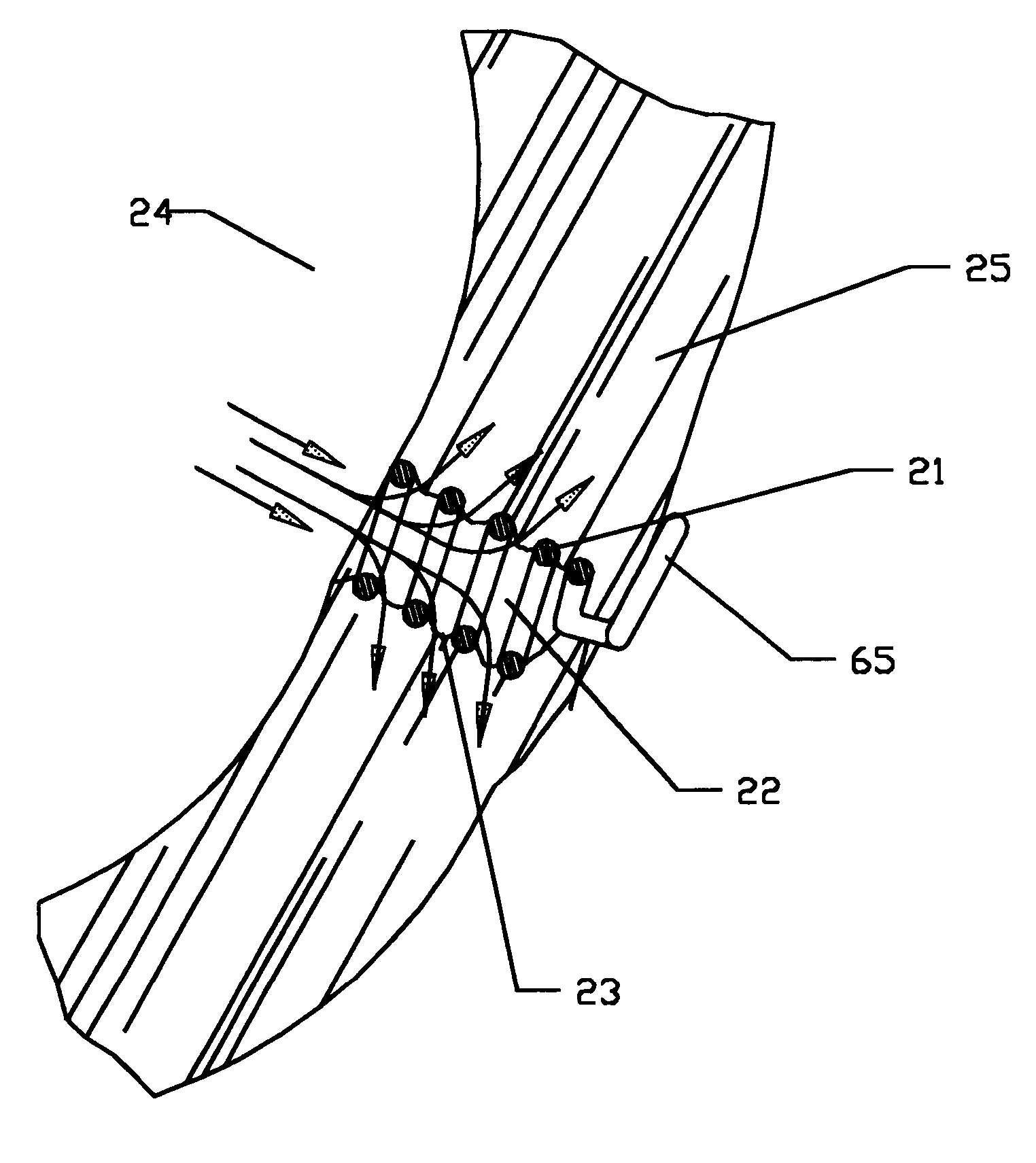
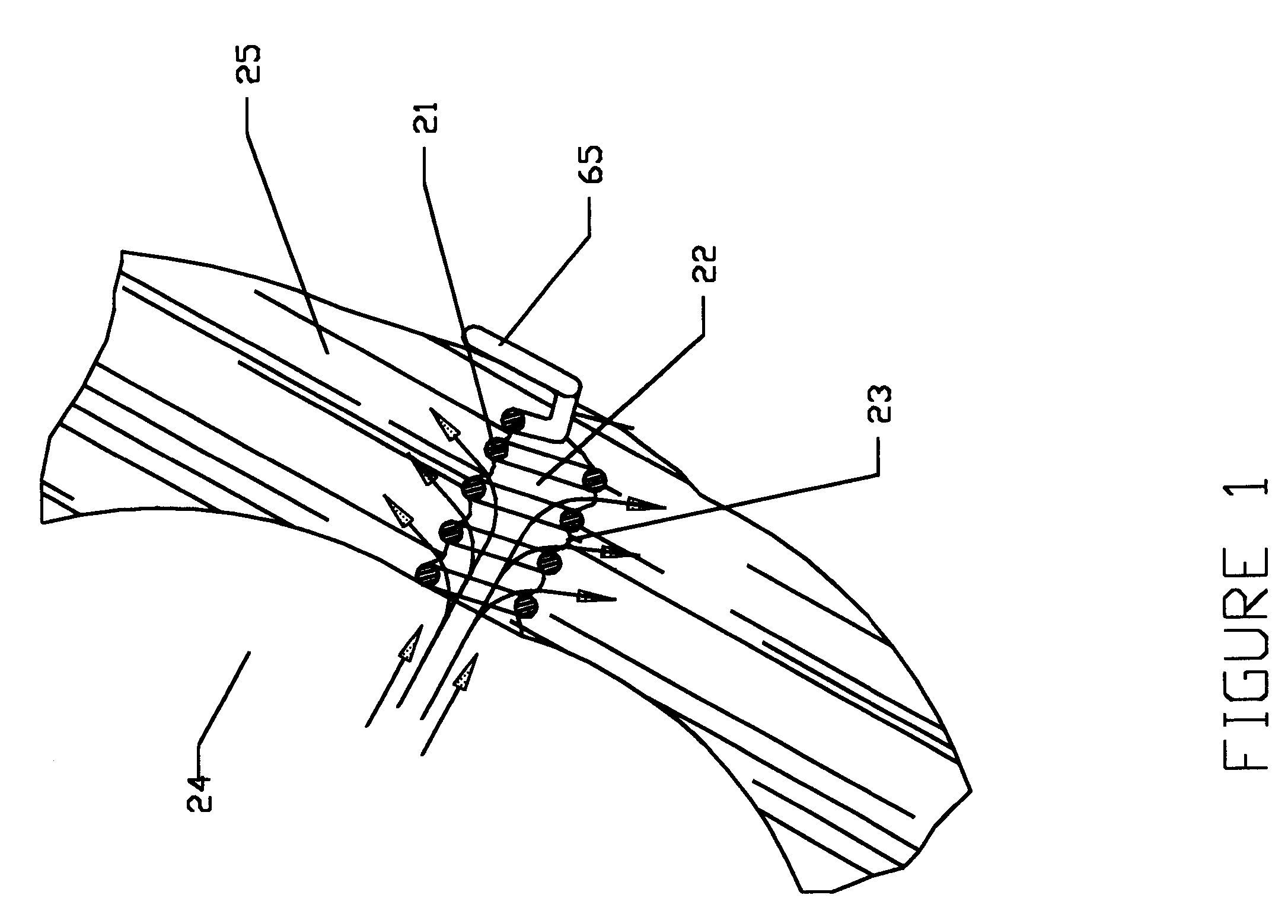
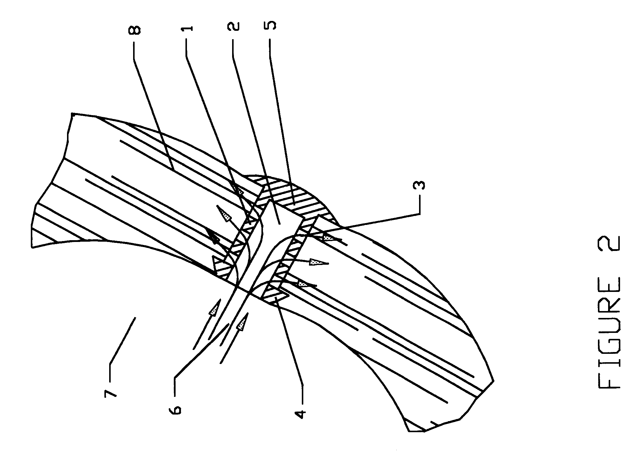
This invention provides implant and needle means for creating and maintaining a patent lumen in the diseased myocardium. This implant provides a conduit for the flow of blood nutrients from the ventricular chamber to the intramyocardial vascular network. This implant can be used as the sole therapy or as an adjunctive therapy to other forms of TMR. Revascularization of the myocardium can be achieved and maintained by creating implanted, needle-made, channels within the myocardial tissue. These channels can allow blood nutrients within the left ventricular cavity to find direct access to ischemic zones within the ventricular wall independent of access through the coronary arteries.
Various configurations of implants are disclosed; including flexible and rigid implants, screw implants, sleeve implants, and others. Manual or powered devices are disclosed for the delivery or placement of implants into a heart wall. The proximal end of each implant terminates at the epicardial surface and provides mechanical holding means to prevent implant detachment and leakage of blood from the ventricle. Each implant is designed so as to maintain an adequate pressure gradient between the left ventricle and the myocardial tissue in order to maintain the flow from the ventricular cavity to the myocardial tissue of blood nutrients.

Problems solved by technology

Symptomatic occlusive coronary artery disease that does not respond to medical or interventional treatment is a major challenge for cardiac surgeons and cardiologists.
The limitation of needle-made channels is early closure (Pifarre, 1969).

Method used


Image

  • Implant device for trans myocardial revascularization
  • Implant device for trans myocardial revascularization
  • Implant device for trans myocardial revascularization

Examples


first embodiment

FIG. 7 shows the construction and method of use of one embodiment of a delivery device for creating a pathway in the heart wall and for placement of a myocardial implant in this pathway. In this first embodiment, a needle obturator 36 carries a myocardial implant 35 having an anchoring wire 37, which may be offset from the myocardial implant, as shown in FIG. 7, or aligned with the myocardial implant, as shown in FIGS. 11 and 12. The obturator and myocardial implant are inserted through the heart wall 38 until the endocardiac surface is reached. After the endocardiac surface 39 of the heart wall is reached, the obturator 36 is removed, as by turning or unscrewing the same, thereby leaving the myocardial implant 35 embedded in the heart wall. Additional improvements include a fluid channel 66 that is formed in the obturator body to provide an indication that the obturator's distal end 67 has crossed the endocardiac surface 39.

second embodiment

FIGS. 8A through 8I show the construction of an alternate myocardial implant and a delivery system for placement of the alternate implant in a heart wall. FIG. 8A shows a delivery system having a pin 40 and handle 41 having a locking device 42. An obturator 43 is mounted in the pin 40. The obturator 43 has a recess 44 (FIG. 8B) to engage the distal end of a myocardial implant 45. The pin 40 has a recess 46 (FIG. 8B) to engage the proximal end of the implant 45.

The method of use involves the placement of the implant 45 over an obturator 43. The pin 40 is then rotated to create a radial stress on the TMR implant 45 (FIG. 8D). The pin 40 is locked to the handle 41 (FIG. 8C). Advancement through the heart wall 50 of the obturator and TMR device 45 is achieved by pressing the obturator through the heart wall (FIGS. 8E, 8F). The pin 40 is released from handle 41 by withdrawing the locking device 42 (FIGS. 8G, 8H). This causes the implant 45 to be released from the obturator 43. The obtura...


PUM


Abstract

A myocardial implant for insertion into a heart wall for trans myocardial revascularization (TMR) of the heart wall. The TMR implant provides for means to promote the formation of new blood vessels (angiogenesis), and has a flexible, elongated body that contains a cavity and openings through the flexible, elongated body from the cavity. The TMR implant includes a coaxial anchoring element integrally formed at one end for securing the TMR implant in the heart wall.

Description

1. Technical FieldThis invention is generally directed to the fields of cardiac surgery and interventional cardiology, and particularly, to mechanical devices and methods suited for improving blood flow to a heart muscle by Trans Myocardial Revascularization (TMR).2. Description of Related ArtSymptomatic occlusive coronary artery disease that does not respond to medical or interventional treatment is a major challenge for cardiac surgeons and cardiologists. The discovery of sinusoidal communications within the myocardium (Wearns, 1993) has motivated researchers to attempt various methods for myocardial revascularization based on the existence of this vascular mesh network. These methods aimed at the delivery of oxygenated blood to the vicinity of the sponge-like sinusoidal plexus in order to restore blood flow to the ischemic myocardium. Several investigators have attempted to deliver oxygenated blood directly from the left ventricle into the myocardial sinusoids by employing needle...

Claims


Application Information

Patent Timeline
Patent Type & Authority Patents(United States)
IPC IPC(8): A61F2/06A61M1/10A61F2/02A61M1/12A61B17/00A61F2/88A61F2/94
CPCA61F2/06A61F2/95A61F2/88A61F2/94A61F2/2493A61B2017/00247A61B2018/00392
Inventor HUSSEIN, HANYSULEK, STANISLAW
Owner MYOCARDIAL STENTS
Learn More