Method of applying an edge electrode pattern to a touch screen and a decal for a touch screen

Inactive Publication Date: 2001-08-28
3M INNOVATIVE PROPERTIES CO
View PDF7 Cites 64 Cited by
  • Summary
  • Abstract
  • Description
  • Claims
  • Application Information

AI Technical Summary

Benefits of technology

It is a further object of this invention to provide such a method and such a decal which allows multiple layers of conductive ink to be applied to the panel in one step thereby eliminating the often difficult and imprecise re-registration of the pattern with respect to the panel.
It is a further object of this invention to provide such a method and such a decal which reduces printing defects and eliminates the need to rework the electrode pattern.
It is a further object of this invention to provide such a method and such a decal which results in improved quality touch screens.
It is a further object of this invention to provide such a method and such a decal which reduces the cost of manufacturing touch screen panels.
It is

Problems solved by technology

The screen printing process, however, can lead to a number of problems when attempts are made to achieve a quality edge electrode pattern.
The most severe problem occurs when printing on non-flat or curved glass substrates.
When printing on curved substrates, this distance varies with the degree of curvature of the substrate resulting in non-uniform thickness of the printed ink.
Furthermore, automated screen-printing equipment, which requires a uniform and repeatable force to push the ink through the printing screen, can not be used with curved screens due to the mismatch of the flat printing screen and the non-flat substrate.
The non-reproducible force used in this manual process leads to further variations in the thickness of the printed ink.
Frequently, this process also leads to fatal defects in the edge electrode pattern such

Method used


Image

  • Method of applying an edge electrode pattern to a touch screen and a decal for a touch screen
  • Method of applying an edge electrode pattern to a touch screen and a decal for a touch screen
  • Method of applying an edge electrode pattern to a touch screen and a decal for a touch screen

Examples


Example

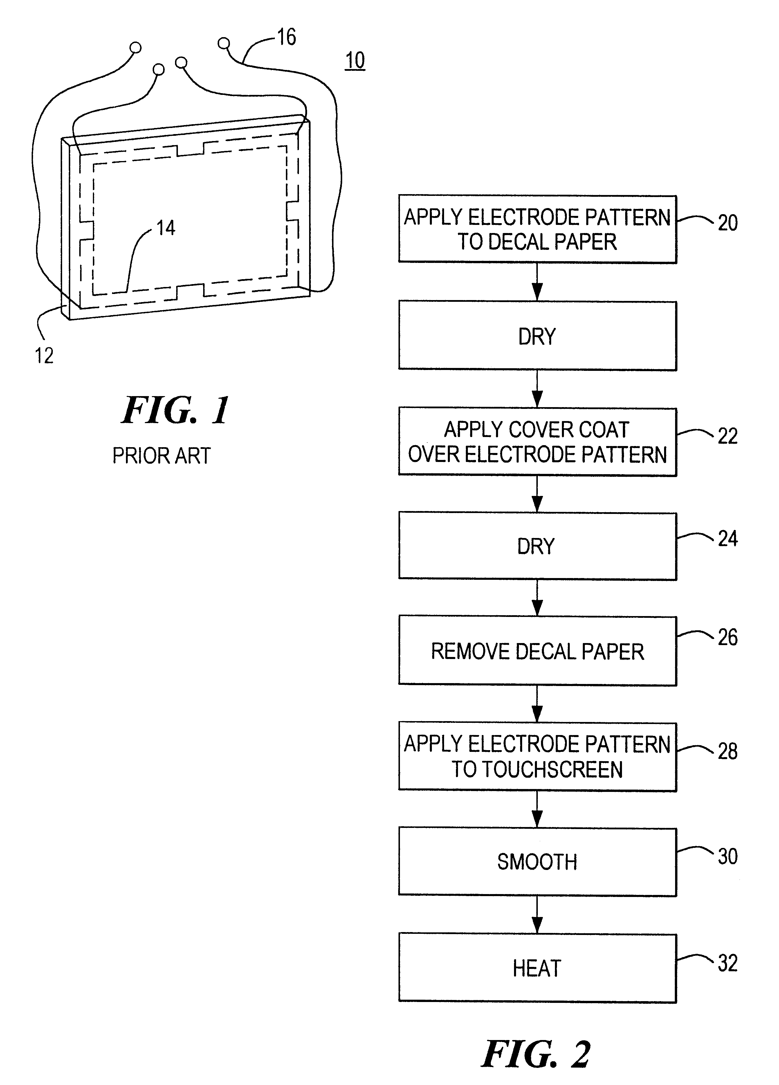
Touch screen panel 10, FIG. 1, typically includes a glass substrate 12 coated with a resistive layer such as tin oxide upon which are deposited edge electrodes 14 usually by screen printing as discussed for example in U.S. Pat. No. 4,198,539. Wires 16 are each connected to a different corner electrode of pattern 14 as shown. As discussed in the Background of the Invention above, these wires are typically taped to the edges of panel 10. In some embodiments, an insulative layer is disposed in a border configuration around the perimeter of panel 10 over edge electrode pattern 14 between edge electrode pattern 14 and wires 16 and in still other embodiments, a conductive noise shield layer and possibly a protective layer may be disposed over the insulative layer. A noise shield border layer may also be screen printed peripherally on the back of the touch screen panel shown in FIG. 1.

As discussed in the Background of the Invention above, when the touch screen panel is curved, it is very d...


PUM

PropertyMeasurementUnit
Dielectric polarization enthalpyaaaaaaaaaa
Pressureaaaaaaaaaa
Electrical conductoraaaaaaaaaa

Abstract

A method of applying an edge electrode pattern to a touch screen panel including printing an edge electrode pattern on decal paper; applying a cover coat over the electrode pattern; removing the decal paper; and transferring the edge electrode pattern to a touch screen panel. A decal to be used in accordance with this method.

Description

This invention relates to a novel method of applying an edge electrode pattern to a touch screen and a decal for applying an edge electrode pattern to a touch screen.BACKGROUND OF INVENTIONTouch screen panels generally comprise an insulative (e.g. glass) substrate and a resistive layer disposed on the insulative substrate. A pattern of conductive electrodes are then formed on the edges of the resistive layer. The conductive electrodes form orthogonal electric fields in the X and Y directions across the resistive layer. Contact of a finger or stylus on the panel then causes the generation of a signal that is representative of the X and Y coordinates of the location of the finger or the stylus with respect to the substrate. In this way, the associated touch panel circuitry can ascertain where the touch occurred on the substrate. Typically, a computer program generates an option to the user (e.g. "press here for `yes` and press here for `no`") on a monitor underneath the touch screen p...

Claims


Application Information

Patent Timeline
IPC IPC(8): G06F3/033H05K3/20H05K3/28G06F3/045
CPCG06F3/045H05K3/207H05K3/28H05K2201/0284Y10T428/24777H05K2203/0531Y10S428/914Y10T428/24917Y10T29/49117H05K2201/09436
Inventor BOTTARI, FRANK J.
Owner 3M INNOVATIVE PROPERTIES CO
Why Eureka
Try Eureka