Induction microscanner

Inactive Publication Date: 2001-09-04
BOARD OF SUPERVISORS OF LOUISIANA STATE UNIV & AGRI & MECHANICAL COLLEGE
View PDF3 Cites 31 Cited by
  • Summary
  • Abstract
  • Description
  • Claims
  • Application Information

AI Technical Summary

Benefits of technology

In another alternative, the electric circuits and magnetic fields may be eli

Problems solved by technology

Limitations of prior mechanical scanners include their relatively large size, high power consumption, and limited scanning frequencies.
Prior electro-optical and ultrasonic devices are expensive, have limited deflection angles, and experience high attenuation of reflected light beams.
Micro-electromechanical scanners based on electrostatic actuation of a moving mirror have been reported, but these devices have achieved only small deflection angles and low efficiencies as compared to electromagnetic devices of approximately the same resonance frequency and size.
These references demonstrated that, while silicon is an excellent structural material for manufacturing a monolithic resonant scanning mirror with very

Method used


Image

  • Induction microscanner
  • Induction microscanner
  • Induction microscanner

Examples


Example

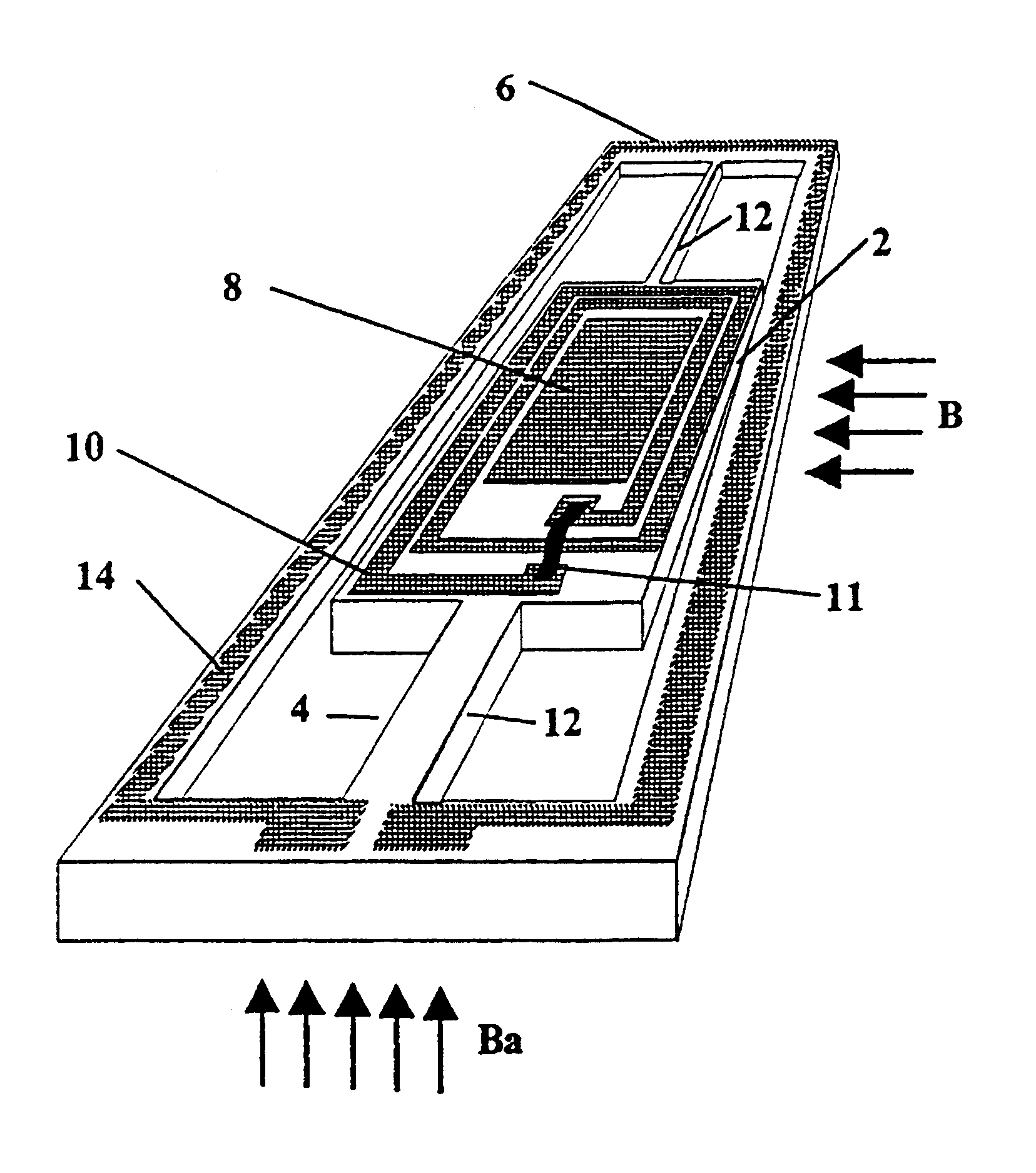
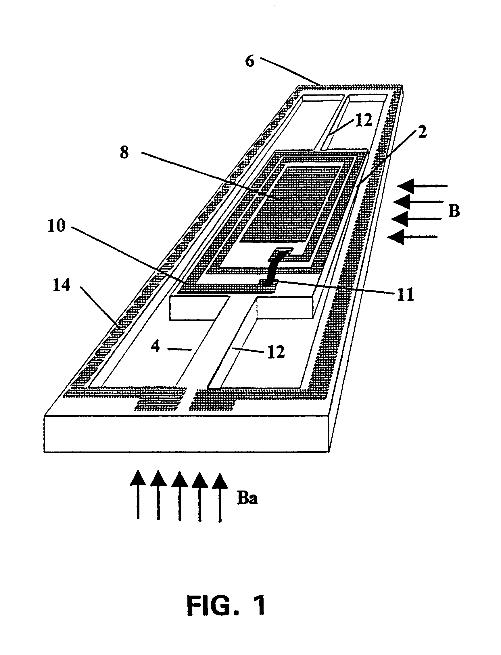
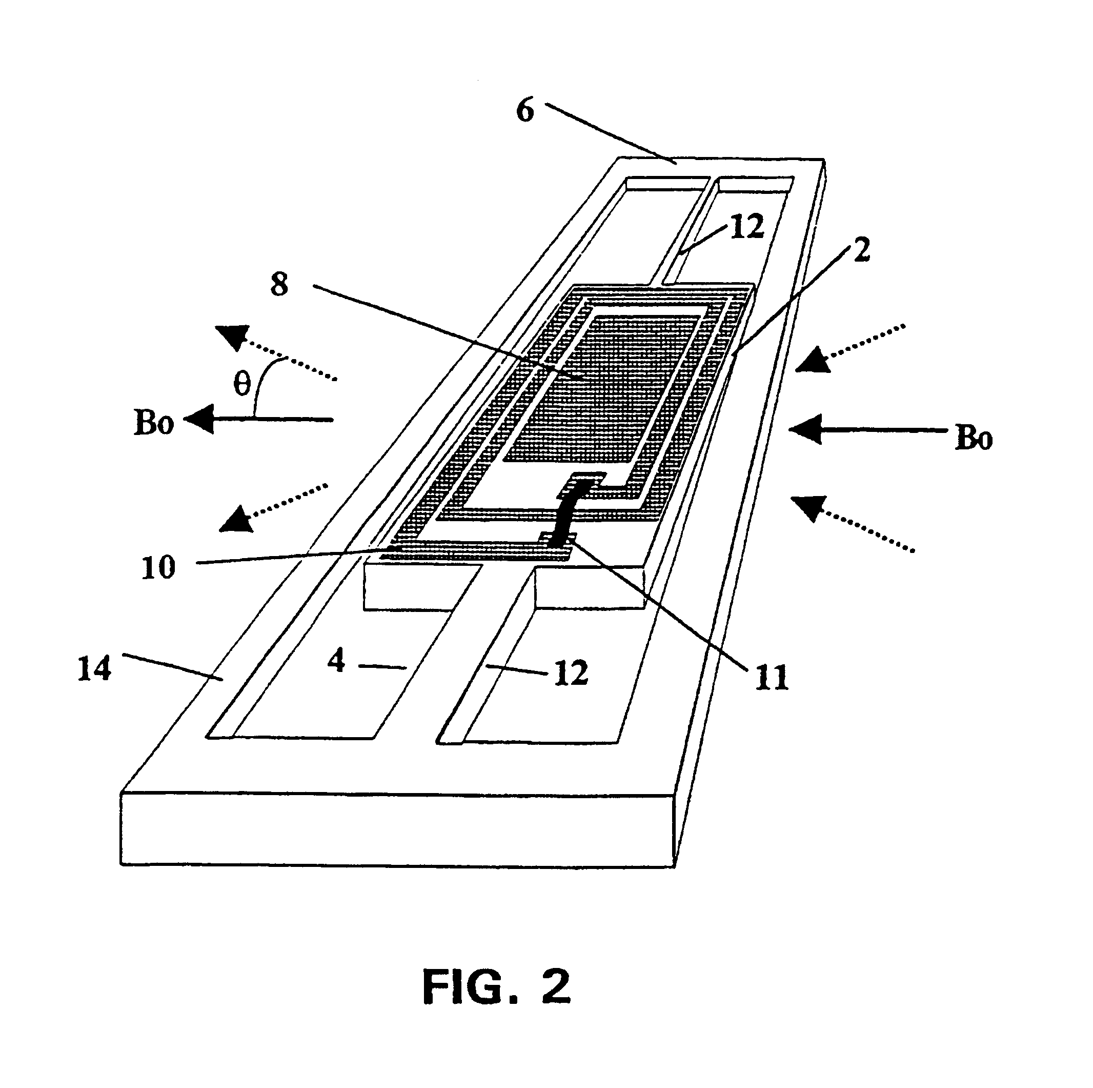
As depicted in the embodiment illustrated in FIG. 1, the novel device has three main sub-systems: a rotor 2, a suspension system 4, and a stator 6. The rotor 2 includes mirror 8 and closed-loop coil 10. As illustrated in FIG. 1, closed-loop coil 10 comprises multiple turns, with the two ends of the coil connected by jumper 11. Coil 10 may also comprise but a single loop, as was done in the prototype embodiment described below. The suspension system 4 connects the rotor 2 to the stator 6. Suspension system 4, comprising torsion bars 12, has one principal degree of freedom, namely that allowing rotation or oscillation of the rotor about the axis of the torsion bars under torque. The stator 6 is a frame that supports the moving parts, the suspension system 4 and the rotor 2. Coil 14 for inductively coupling a power supply (not illustrated) to the coil 10 of the rotor (in the case of amplitude-modulation excitation) may optionally be part of the stator (as depicted in FIG. 1), or it may...


PUM


Abstract

A micro-electromechanical scanner is disclosed for the efficient, controlled deflection of light beams. The device comprises a moving rotor, a suspension system, and a stator. The rotor comprises a closed-circuit coil and a mirror. The suspension system may be, for example, a set of torsion bars on which the rotor is mounted. The stator may be, for example, a rectangular frame holding the suspension system. When placed in a constant magnetic field and excited by an alternating magnet field, the rotor oscillates at the frequency of the alternating magnetic field, All else being equal, the highest deflection angles occur at the natural mechanical resonance frequency of the rotor-suspension combination. Compared to conventional devices, the novel device can be smaller, can be less expensive, can consume less power, and may exhibit higher deflection angles over a given time scale than other micromechanical devices operating on different actuation principles. The novel device may be used, for example, to replace the scanning devices currently used in laser printers, laser bar-code readers, and laser image projectors (e.g., large screen televisions). The control electronics may optionally be manufactured on the same device, eliminating the need for a separate controller and reducing costs.

Description

This invention pertains to scanners for controlling the direction of propagation of a light beam, particularly to micro-mechanical scanners for controlling the direction of propagation of a light beam.Scanners are used to control the direction of propagation of a light beam. Scanners are frequently found in devices such as laser printers and bar-code readers. The three general categories of previous scanner devices are mechanical, electro-optical, and ultrasonic devices. The most commonly used devices have been mechanical scanners, which are based upon a mirror or set of mirrors attached to the turning axis of an electromagnetic actuator such as a galvanometer or electric motor. Limitations of prior mechanical scanners include their relatively large size, high power consumption, and limited scanning frequencies. Prior galvanic scanners are typically 20.times.20.times.50 mm or larger, with a mass exceeding 50 grams (excluding control electronics), a typical power consumption of 1 Wat...

Claims


Application Information

Patent Timeline
IPC IPC(8): G02B26/08H02K33/00
CPCH02K33/00G02B26/085
Inventor FERREIRA, LUIZ OTAVIO S.
Owner BOARD OF SUPERVISORS OF LOUISIANA STATE UNIV & AGRI & MECHANICAL COLLEGE
Why Eureka
Try Eureka