This hopefully leads to light weight and low costs.
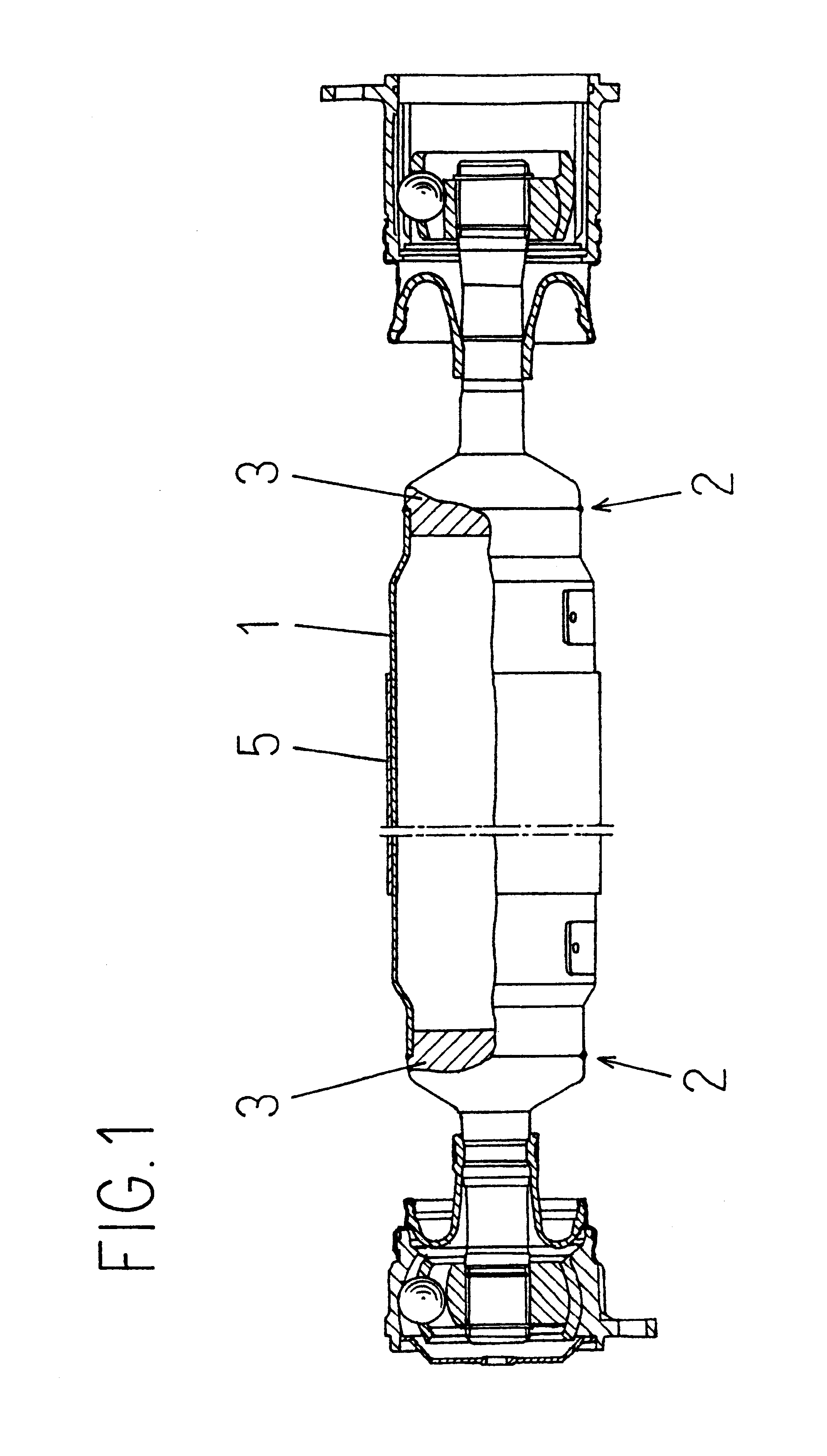
However, its joint portion can hardly be integrally molded with FRP in view of the rigidity and strength.
However, according to these conventional methods, there are various problems in molding, such as difficulty in
processing a shaft end portion, a need for increasing the outer
diameter for ensuring the strength of the joining portion, or an additional need for taking measures against slipping-off in an axial direction for ensuring reliability.
Caulking a hollow shaft made of FRP or press-fitting a
metal component into a shaft core of a hollow shaft involves a serious
disadvantage of lack in a long-term reliability caused by decrease in a
binding force due to
creep or
stress relaxation at the FRP portion, leading to possible sliding in a circumferential direction or possible slipping-off in an axial direction.
This leads to problems in joining, such as generation of cracks in the FRP portion during the process or unavoidable
creep or
stress relaxation when in use.
Further, as described in Japanese Laid-open Patent Publication No 53-71422, by simply using a metal
pipe and an FRP pipe in combination as materials, an interfacial exfoliation is generated at an interface between a reinforcing fiber and matrix inside the FRP layer when the composite hollow shaft is deformed by a torque in the circumferential direction, so that it cannot be practically applied to a intermediate shaft of a propeller shaft to be mounted onto a car or the like.
In other words, if the composite hollow shaft is used under a repeated torque typically acting in a car or the like, it is not possible to maintain a desired rigidity of the composite hollow shaft portion constructed with the metal pipe and the FRP layer.
On the other hand, if one wishes to increase the interface strength between the reinforcing fiber and the matrix to be larger than 200 MPa, a special surface treatment on a fiber surface must be employed in combination with special matrix, making its production difficult.
In other words, if one attempts to meet the required the first
critical speed of rotation by a metal pipe alone, it will have a large
diameter and a large weight.
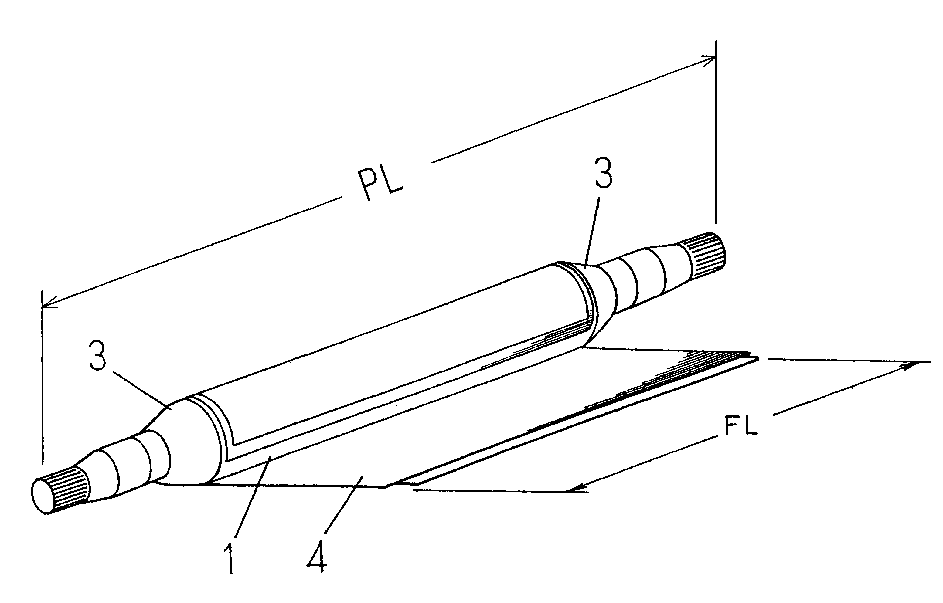
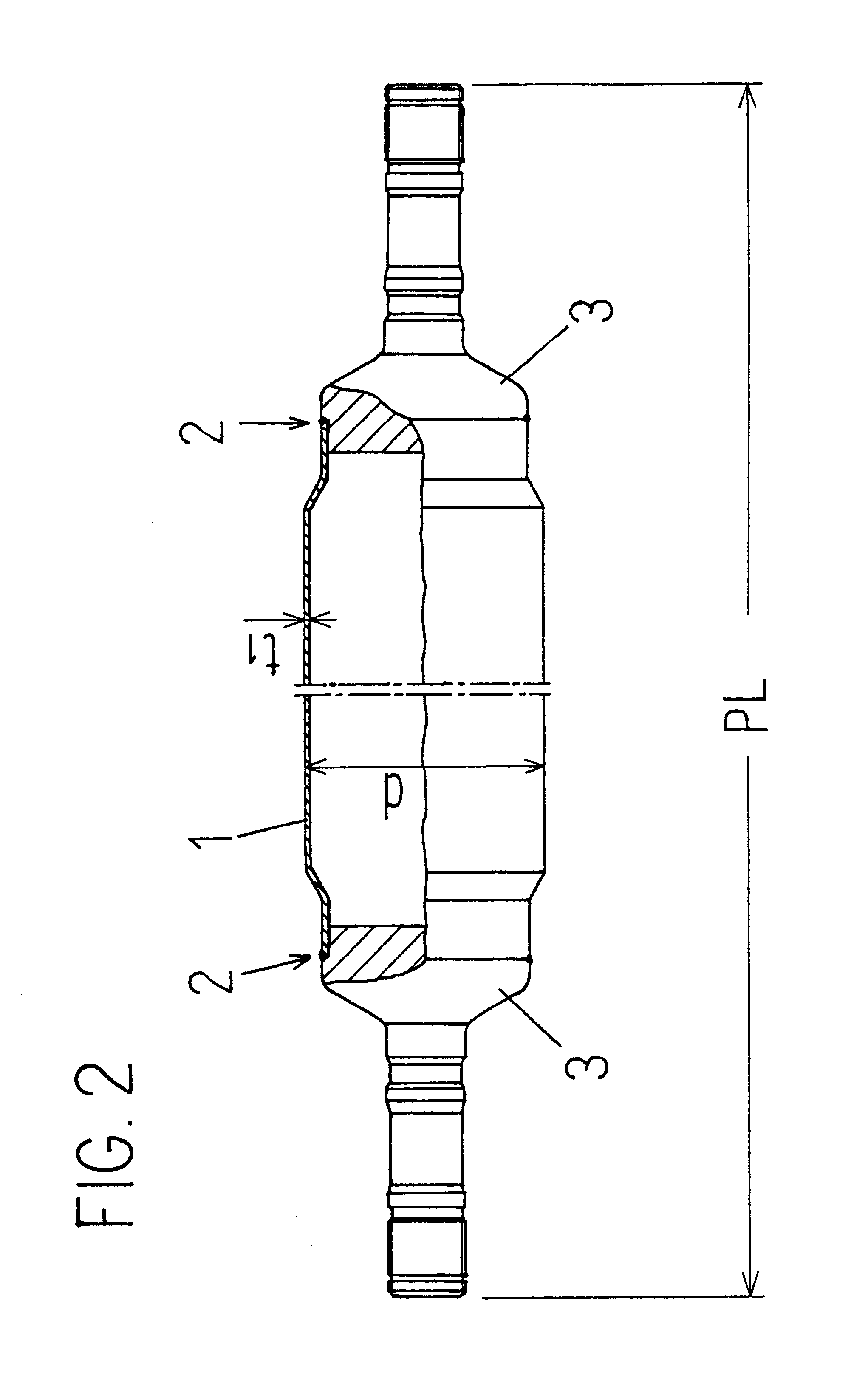
If the value of FL / PL is smaller than 0.1, it is difficult to achieve a
flexural rigidity that satisfies the required the first
critical speed of rotation even if an FRP layer having a high modulus of elasticity is wound around.
If the length is smaller than 10 mm, it leads to a
disadvantage that a prepreg constituting a 0.degree. layer is not wound well onto the metal pipe, whereas if the length is larger than 3000 mm, the assembling work into the car will be difficult even if it is used in trucks or the like.
If the outer
diameter is smaller than 10 mm, the transmitted torque will be unsatisfactory as a propeller shaft to be used in an automobile even if an FRP layer is formed on the outer circumference portion.
If the outer diameter is larger than 250 mm, a problem arises such as interference with other components for passenger cars.
If the metal pipe has a thickness smaller than 1 mm, there will be a fear that the metal pipe is broken in transporting the metal pipe or in molding the FRP layer.
Also, it will be difficult to design the inner diameter and the thickness of the metal pipe to satisfy only the static
torsional strength required in propeller shafts for passenger car and, even if it could be designed, the pipe diameter would be large.
If the thickness of the metal pipe is thicker than 10 mm, the propeller shaft will be too heavy for use in an automobile, thus failing to achieve the aforementioned object of light weight.
If the thickness of the prepreg is smaller than 5 .mu.m, wrinkles are liable to be generated in the wrapping process and, when a torque is applied to the composite hollow shaft, the wrinkled portion may possibly be a starting point of cracks.
If the thickness of the prepreg is larger than 600 .mu.m, it is difficult to wind it due to its thickness and, even if it is wound, there will be a comparatively large difference in level in the appearance of the composite hollow shaft.
This difference in level may possibly make it difficult to keep a balance if it is used as a intermediate shaft of a propeller shaft.
If the filament diameter of the PAN-based carbon fiber is less than 1 .mu.m, then the cost of an
acrylic fiber as a
source material will be expensive and the control will be difficult in
processing into the carbon fiber by firing, thereby increasing the price of the fiber and making it impossible to establish a low-cost shaft.
On the other hand, if the filament diameter of the PAN-based fiber exceeds 20 .mu.m, it is not possible to produce a prepreg for use by the sheet wrapping method.
However, in the case of the tow-form, the fiber is molded to have a small thickness and a large diameter by the
filament winding method or the pultrusions while dipping it in an uncured matrix resin.
By pultrusions, it is comparatively difficult to form a layer having an orientation angle of 90.degree..
Since the ambient temperature of the propeller shaft used as a
mechanical power transmission shaft of an automobile is about 60.degree., there will possibly be a serious problem such as destruction and the resin cannot be used as a matrix if the
heat resistance after
epoxy curing is less than 60.degree..
), if a curing treatment is performed after winding a carbon fiber around an aluminum pipe, a practical problem may possibly be raised such that a
compression stress remains in the axial direction in the carbon fiber during cooling after cure owing to the difference in the
thermal expansion coefficient between the aluminum pipe and the carbon fiber prepreg.
On the other hand, if the ratio of the circumferential direction layer (90.degree. layer) is larger than 20%. the thickness of the laminate portion will be thick for imparting a flexural rigidity in the fiber construction of the FRP layer having a two-layer structure including the 0.degree. layer and the 90.degree. layer, thereby leading to lack in rationality from the viewpoint of economy and light weight.
In other words, if the
fiber orientation angle relative to the axial direction of the metal pipe is less than .+-.5.degree., the value of the
thermal expansion coefficient in the circumferential direction of the shaft cannot be controlled to be 11 mm / mm / .degree. C. or less, and also cracks are liable to be generated (=occurred) owing to the
residual stress in the laminate portion of the FRP material in the axial direction in the molding process.
On the other hand, if the
fiber orientation angle is larger than .+-.30.degree., the thickness of the FRP layer portion will be thick if a desired rigidity is to be established in the composite hollow shaft portion constructed by the metal pipe and the FRP layer, thereby leading to lack in rationality from the viewpoint of economy and light weight.

