System for determining analyte concentration

a technology of analyte concentration and system, applied in the direction of fluorescence/phosphorescence, material analysis, instruments, etc., can solve the problems of difficult to build a multi-well biosensor, tedious washing step, and part of the technician

Inactive Publication Date: 2001-09-11
UNIV OF UTAH RES FOUND
View PDF5 Cites 148 Cited by
  • Summary
  • Abstract
  • Description
  • Claims
  • Application Information

AI Technical Summary

Benefits of technology

The present invention discloses a method and apparatus for determining the presence and/or concentration of one or more analytes in a sample. In one embodiment of the invention, a method of simultaneously determining the presence of a plurality of analytes in a sample is disclosed. The method of determining the presence of a plurality of analytes comprises one or more of the following steps, either individually or in combination: providing a biosensor having a waveguide and a plurality of patches disposed within a well defined in the waveguide, a first patch of the plurality of patches having a first type of capture molecule associated therewith, and a second patch of the plurality of patches having a second type of capture molecule associated therewith; introducing a sample believed to contain a plurality of analytes into the well; introducing at least one type of tracer molecule into the well, the tracer molecule comprising a fluorescent label bonded to a

Problems solved by technology

This problem is particularly true for detection of analytes present at concentrations below nanomolar, as is the case for many analytes of interest in body fluids including blood, serum and urine.
However, the wash step is tedious, and care on the part of the technician is required to produce repeatable and accurate results.
However, in a typical prior art evanescent light device such as that of Block et al, U.S. Pat. No. 4,909,990 issued Mar. 20, 1990, the waveguide is a fiber optic rod whose shape makes it difficult to build a multi-well biosensor.
Previous methods of immobilizing antibodies to optical substrates in evanescent biosensors also present some problems causing reduction in sensitivity.
This approach has at least two significant disadvantages due to the fact that many proteins have multiple lysine residues.
First, the presence of multiple potential coupling sites (multiple lysine residues) results in multiple random orientations of antibodies on the substrate

Method used


Image

  • System for determining analyte concentration
  • System for determining analyte concentration
  • System for determining analyte concentration

Examples


Embodiment Construction

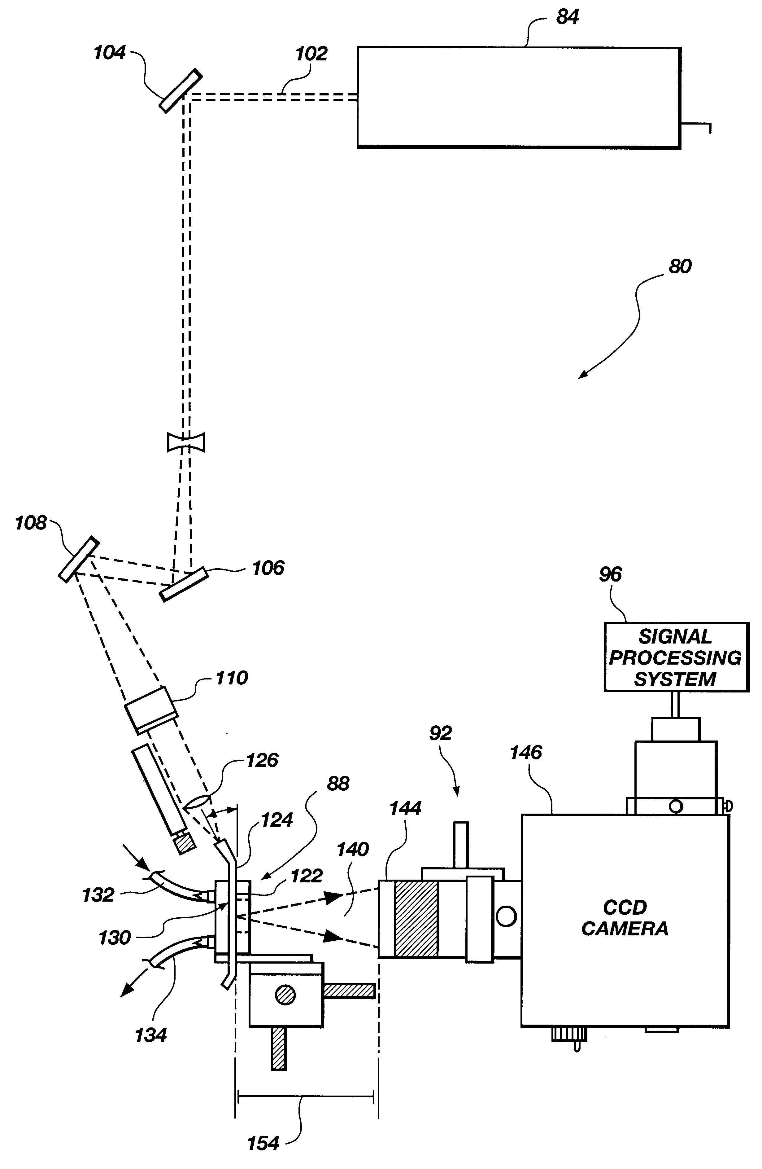
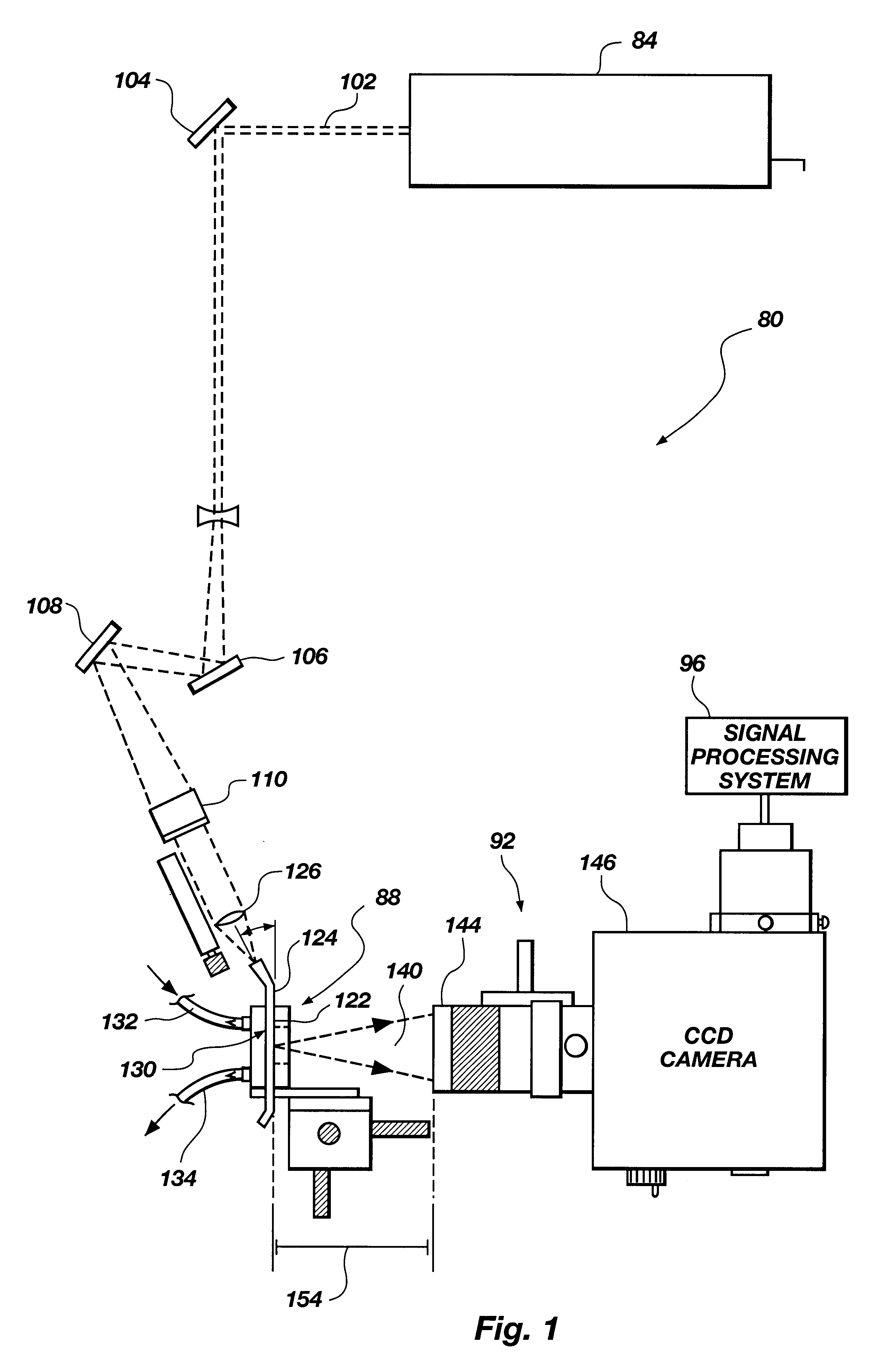
Referring to FIG. 1, a biosensing system, generally 80, includes a light source 84, a biosensor 88, and an optical detection system 92. As used herein, the term "light" refers to electromagnetic radiation, and is not limited to the visible spectrum. Biosensor 88 contains an assay that emits fluorescence when excited by light from light source 84 depending on whether or not analyte is present in a liquid sample being analyzed in the biosensor. The fluorescence is detected by an optical detection system 92. Biosensing system 80 may further include a signal processing system 96 that analyzes signals from optical detection system 92.

A. Overview of System Components

In one embodiment, light source 84 is a laser that produces a light beam 102 that is directed by means of mirrors 104, 106, and 108 to biosensor 88. A 45.degree. angle mirror 110 may be positioned for making beam 102 a vertical beam prior to focussing the beam onto biosensor 88.

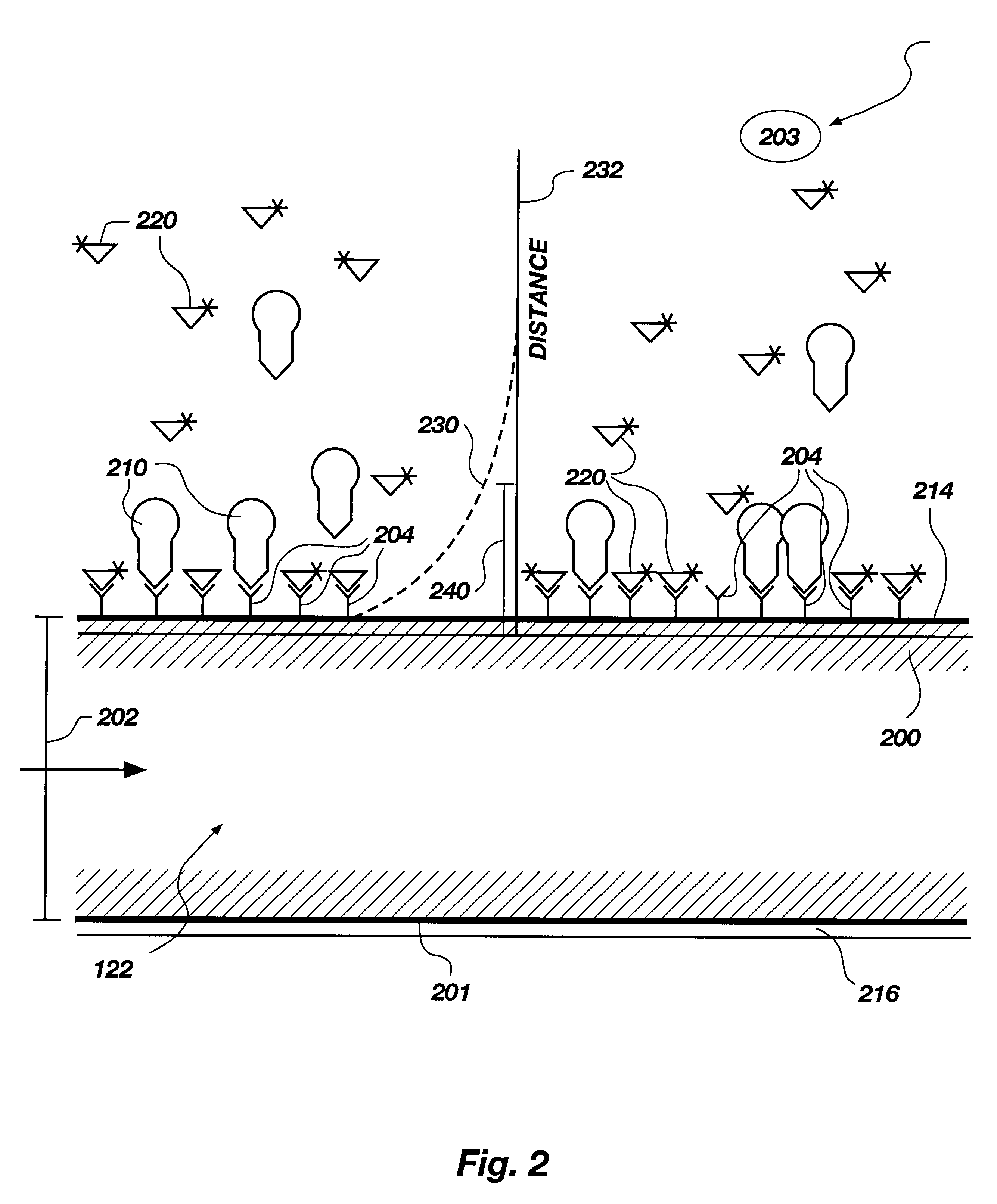
Biosensor 88 includes an optical substrate or wav...


PUM


Abstract

The present invention relates to a system (80) for determining analyte concentration. The system (80) includes an optical detection system (92) that detects fluorescence from fluorescent binding assays in a biosensor (88). A processing system (96) may be used to determine analyte concentration from the fluorescence detected by the optical detection system (92). The optical detection system (92) may include photodetectors with or without in series lenses. Alternatively, a CCD camera (146) may be used.

Description

This present invention relates to a system and method for determining analyte concentration including an optical detection system that detects fluorescence from fluorescent assays, and a processing system that determines analyte concentration from the fluorescence.Biosensor apparatus based on optical detection of analytes by fluorescence of tracer molecules, have attracted increasing attention in recent years. Such apparatus are useful for both diagnostic and research purposes. In particular, biosensors for a solid-phase fluoroimmunoassay, in which a capture molecule such as an antibody or antibody fragment specific to the desired analyte is immobilized on a substrate, and binding of the analyte to the antibody results either directly or indirectly (for example, by means of a labelled tracer) in a fluorescence signal, are becoming an important class of optical biosensor.In most solid-phase fluoroimmunoassays, to achieve adequate sensitivity a "wash" step is required to remove unboun...

Claims


Application Information

Patent Timeline
IPC IPC(8): G01N33/543G01N21/64G01N33/552
CPCG01N21/6452G01N33/54373G01N21/648
Inventor HERRON, JAMES N.CHRISTENSEN, DOUGLAS A.
Owner UNIV OF UTAH RES FOUND
Why Eureka
Try Eureka