Method for the ultrasonic peening of large sized annular surfaces of thin parts

a technology of annular surfaces and thin metal parts, applied in vibratory devices, abrasion apparatuses, manufacturing tools, etc., can solve the problems of difficult to achieve optimum exposure to peening, inability to absorb loading, and inability to penetrate large-scale annular surfaces, etc., to achieve the effect of improving the fatigue strength of the metal part, reducing the initiation and propagation of cracks, and sufficient kinetic energy

Inactive Publication Date: 2001-09-18
SN DETUDE & DE CONSTR DE MOTEURS DAVIATION S N E C M A
View PDF5 Cites 54 Cited by
  • Summary
  • Abstract
  • Description
  • Claims
  • Application Information

AI Technical Summary

Benefits of technology

It is known practice for the surfaces of metal parts to be peened by blasting with microbeads. By impacting the surface of the metal part with a small angle of incidence with respect of the perpendicular to this surface and with sufficient kinetic energy, the microbeads cause permanent compression of the surface to a small depth. This compression inhibits the initiation and propagation of cracks at the surface of the metals part and thus improves the fatigue strength of that metal part.
A method such as this has the effect of improving the uniformity of the peening over the entire surface that is to be peened. It has been noted that this uniformity reduces the deformations of the part during peening and the residual deformation of the part when peening is finished. The loadings imposed on the part during peening remain roughly uniform across the entire peened surface. The first problem is thus solved.
A particular advantage of the present method is that it allows significant and thorough peening. Thus, more optimal peening on thin parts may be achieved without deformation. It will be understood that, during peening in accordance with present invention, the loadings imposed on the part remain uniform.

Problems solved by technology

A number of difficulties are encountered in peening these thin metal parts.
This is because thin metal parts are unable, without deforming, to absorb the loadings caused by the compressive stresses resulting from the microbeads of heavy peening.
However, such optimum exposure to peening is difficult to achieve because peening nozzles are difficult to adjust and are not stable.
Insufficient peening does not give the anticipated strength, but additional peening to achieve the optimum exposive may lead to excessive peening which causes irreparable surface damage to the metal part, with a resultant reduction in the strength of that metal part.
However, the method of FR 2689431 does not allow the peening of thin circular metal parts, as these circular metal parts begin to deform very early in the peening operation.
Otherwise, over rotation would produce a localized excess of peening on a zone of overlap, whereas under rotation would give rise to a gap of localized lack of peening which would be difficult to correct without giving rise to excessive peening in a region immediately adjacent the original gap of lack of peening.
A first problem, therefore, is that of peening thin and circular parts whose dimensions exceed those of the peening chamber, without deforming the parts.
A second problem is that of guaranteeing uniform peening across the entire surface that is to be peened.
Furthermore, it is stated particularly at page 7 lines 24-34 that a higher speed leads to insufficient peening whereas a lower speed leads to "excessive work hardening".

Method used


Image

  • Method for the ultrasonic peening of large sized annular surfaces of thin parts
  • Method for the ultrasonic peening of large sized annular surfaces of thin parts

Examples


Embodiment Construction

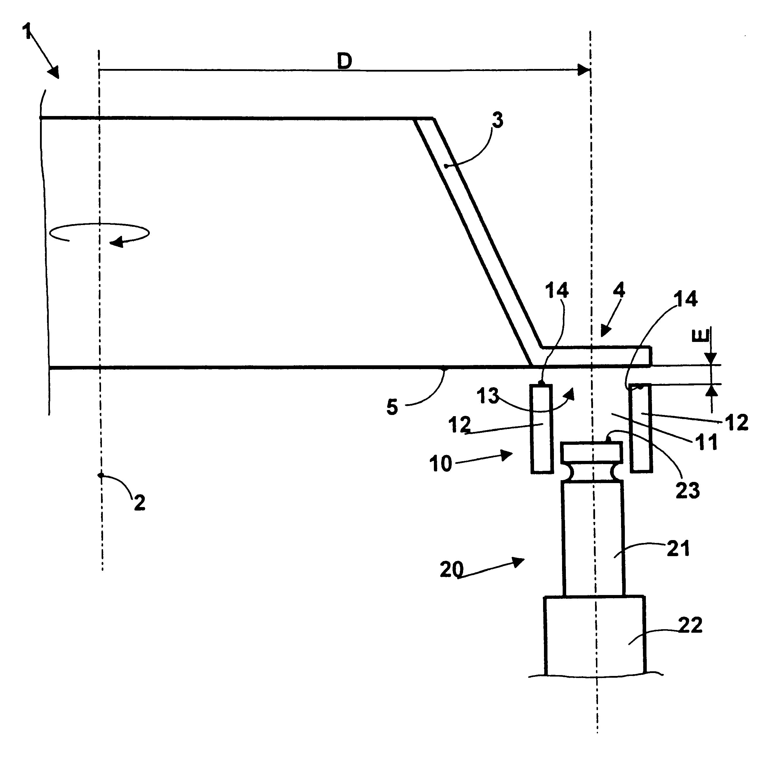
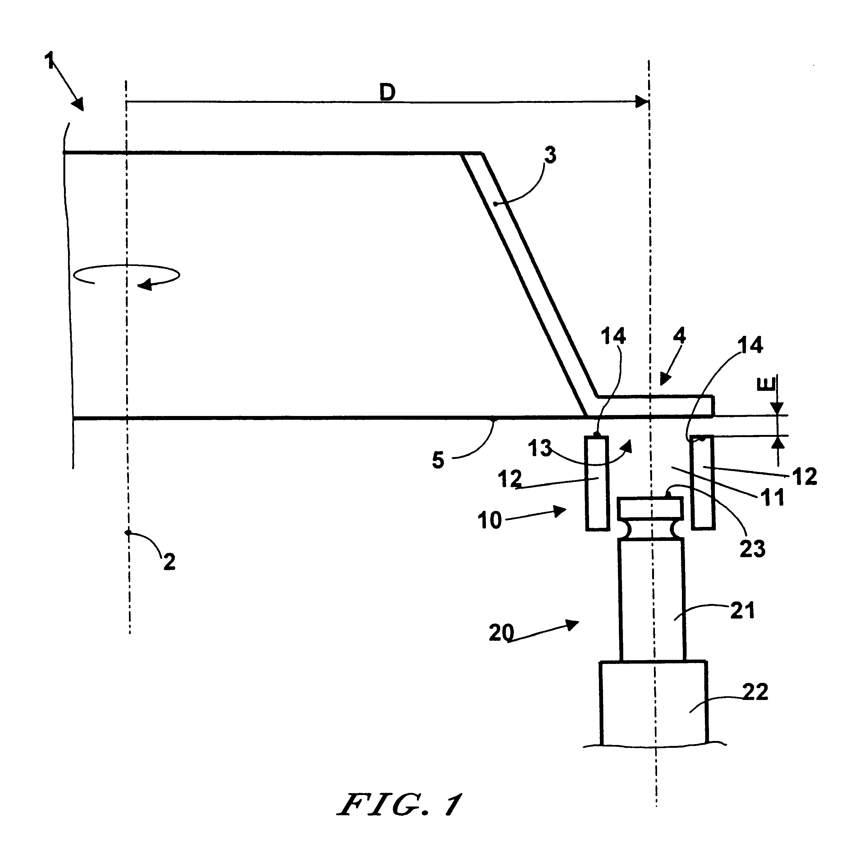
Referring to the drawing, the part 1 is an aircraft turbine engine conical rotor support having a thin wall and with a geometric axis 2 of revolution. The part 1 comprises a frustoconical barrel 3, the larger-diameter end of which is extended radially by a flange 4. The flange 4 itself comprises a bearing surface 5 that is to be peened. The bearing surface 5 is annular, flat and radial.

Use is made of chamber 10 inside which a mist of microbeads 11 is sustained. This chamber is laterally delimited by a wall 12 and comprises an opening 13 the edges of which are referenced 14. Use is also made of a vibrator 20 consisting of a sonotrode 21 brought into resonance via one of its ends by a vibration generator 22 which is usually of the quartz type. The other end of the sonotrode 21 comprises a vibrating and essentially flat surface 23. The vibrating surface 23 is placed at the bottom of the chamber 10 and faces towards the opening 13. The vibration generator 22 sets the sonotrode 21 into l...


PUM

PropertyMeasurementUnit
diameteraaaaaaaaaa
frequenciesaaaaaaaaaa
diameteraaaaaaaaaa

Abstract

A method of so-called "ultrasonic" peening is described for peening large sized annular surfaces on thin parts. The method uses a microbead mist vibrated in a chamber with an opening so that the surface that is to be peened makes at least five movements past the opening of the peening chamber during peening so as to reduce deformation of the part.

Description

1. Field of the InventionThe invention relates to a method of so-called "ultrasonic" peening using a mist of microbeads inside a chamber and more particularly to a method for peening large sized annular surfaces on thin parts.2. Summary of the Prior ArtIt is known practice for the surfaces of metal parts to be peened by blasting with microbeads. By impacting the surface of the metal part with a small angle of incidence with respect of the perpendicular to this surface and with sufficient kinetic energy, the microbeads cause permanent compression of the surface to a small depth. This compression inhibits the initiation and propagation of cracks at the surface of the metals part and thus improves the fatigue strength of that metal part.The microbeads are commonly ball bearings. They are usually made of ceramic or steel with a diameter in the range 0.2 mm to 4 mm. Peening is performed inside a closed booth using nozzles supplied both with compressed gas and with microbeads, the compres...

Claims


Application Information

Patent Timeline
Patent Type & Authority Patents(United States)
IPC IPC(8): C21D7/06C21D7/00C21D1/04B24C1/10
CPCB24C1/10B24C5/005C21D7/06Y10T29/479C21D1/04
Inventor DUQUENNE, CATHERINE DOMINIQUE BEATRICEGIFFARD, VERONIQUE CHRISTIANE RAYMONDEGUELDRY, GERARD MICHEL ROLANDMONS, CLAUDE MARCEL
Owner SN DETUDE & DE CONSTR DE MOTEURS DAVIATION S N E C M A
Why Eureka
Try Eureka