

Production of layered engineered abrasive surfaces
a technology of engineered abrasives and layered coatings, which is applied in the direction of manufacturing tools, grinding devices, other chemical processes, etc., can solve the problems of not settling to an essentially uniform layer coating when deposited on the substrate, uncovered new unused abrasive particles, and difficult to achieve the effect of absorbing the abrasive particles,
- Summary
- Abstract
- Description
- Claims
- Application Information
AI Technical Summary
Benefits of technology
Problems solved by technology
Method used
Image

Examples
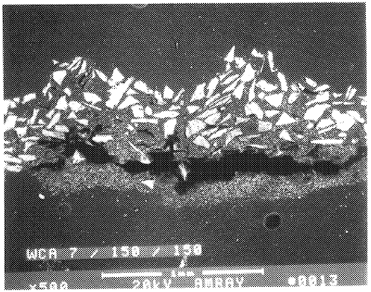
example 1
First layer: 7 micron alumina in a 68% solids slurry.
Second layer: 97 micron alumina in a 70% solids slurry
Surface Powder layer: 97 micron alumina.
In FIG. 1 it is possible to distinguish clearly the first layer from the second but the surface powder layer can not readily be distinguished from the second layer except by the absence of binder all round the grains on the surface.
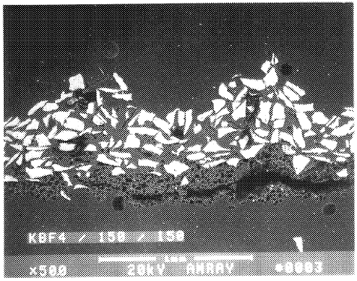
example 2
First layer: 20 micron potassium fluoroborate in a 65% solids slurry.
Second layer: 97 micron alumina in a 70% solids slurry
Surface Powder layer: 97 micron alumina.
In FIG. 2 it is possible to distinguish the KBF.sub.4 layer wherein the particles are darker but again the second layer and the powder layer, having the same abrasive particles included are distinguished only by their location at the surface of the binder layer.
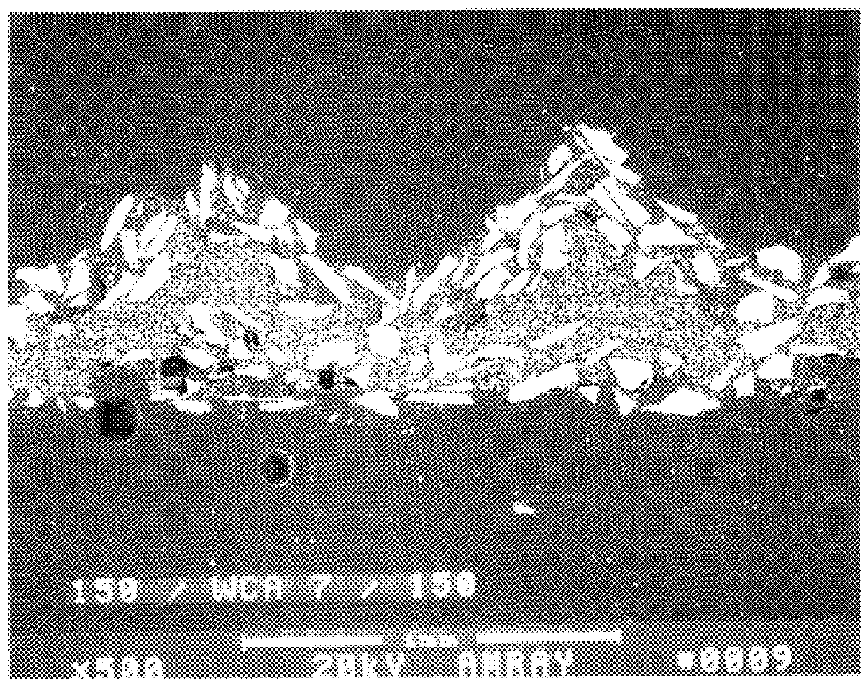
example 3
First layer: 97 micron alumina in a 70% solids slurry.
Second layer: 7 micron alumina in a 68% solids slurry
Surface Powder layer: 7 micron alumina.
FIG. 3 shows the cross-section of this product.
PUM
| Property | Measurement | Unit |
|---|---|---|
| abrasive | aaaaa | aaaaa |
| color | aaaaa | aaaaa |
| surface smoothness | aaaaa | aaaaa |
Abstract
Description
Claims
Application Information