Electronic bordering system

Inactive Publication Date: 2001-10-09
HUSQVARNA AB
View PDF7 Cites 269 Cited by
  • Summary
  • Abstract
  • Description
  • Claims
  • Application Information

AI Technical Summary

Benefits of technology

will become more apparent from the detailed description of

Problems solved by technology

However, it has taken a long time before such kind of tool has reach the market The solar cell driven lawn mover, called Solar Mower, is an example of that kind of product.
On the other hand, the microcomputer cannot in any way separate the magnetic field on the outside from that on the inside of the border cable.
Considering the great disadvantage it means to come outside the border cable the lawn mover must therefore change direction alrea

Method used


Image

  • Electronic bordering system
  • Electronic bordering system
  • Electronic bordering system

Examples


Embodiment Construction

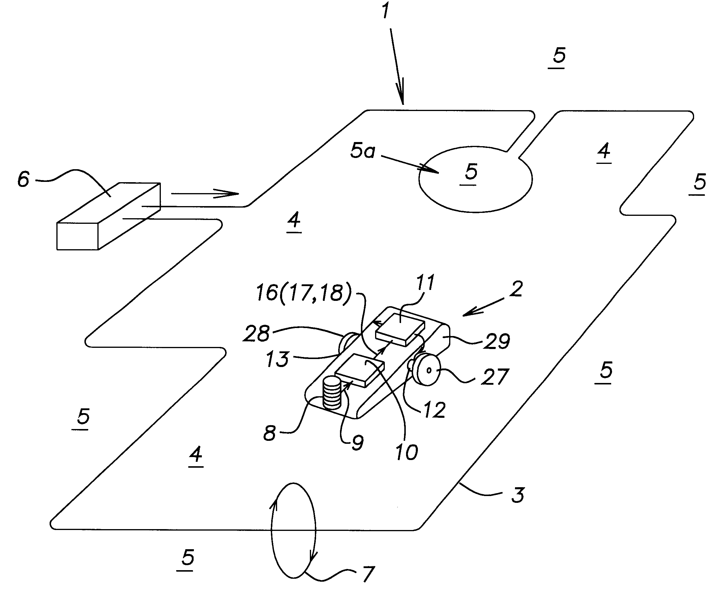
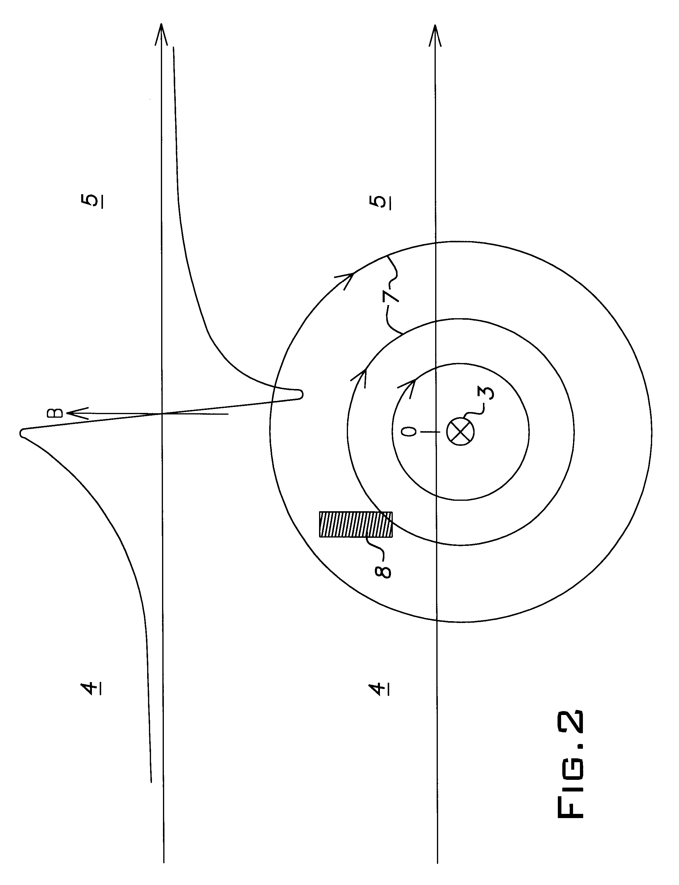
In the schematical FIG. 1 numeral reference 1 designates an electronic bordering system according to the invention. Numeral reference 2 designates a working tool. It is intended to be a lawn mover, which is shown somewhat enlarged, for the sake of clarity. For the same reason only the components which are of interest for the electronic bordering system are shown. The remaining components, such as a knife disc for example, are lying concealed under the tool's cover 29. The border cable 3 is in this case preferably placed a bit under the ground. In other applications, such as a vacuum-cleaner, or a floor-polishing machine, it could be placed on the floor, or above the floor, for example underneath the sealing. The border cable is an electric cable, such as a common copper wire of single-core type, but naturally also double-core type can be used. The border cable 3 is connected to a signal generator 6. The border cable separates an inner area 4 from an outer area 5. The bordering area ...


PUM


Abstract

An electronic bordering system for a working tool in which a border cable is placed above, under or on ground or floor, so that it separates an inner area within the border cable from an outer area. The working tool is preferably intended for attendance of ground or floor. A signal generator feeds the border cable with current, whose magnetic field affects at least one sensing unit located on the working tool, so that the sensing unit emits signals to a control unit, which in cooperation with an engine control, or a signal system for a driver, and at least one driving source directs the tool's movement in order to prevent it from remoting from the inner area. The signal generator feeds the border cable with current containing at least two alternating-current components of different frequency, and the components are lying in a known relation of time to each other.

Description

The subject invention refers to an electronic bordering system for a working tool, in which system a border cable, i.e. an electric cable, is placed above, under or on ground or floor, so that it separates an inner area within the border cable from an outer area, which working tool is preferably intended for attendance of ground or floor, such as grass cutting, moss-scratching, watering, vacuum-cleaning, polishing, transportation etc., and a signal generator feeds the border cable with current, whose magnetic field affects at least one sensing unit located on the working tool, so that the sensing unit emits signals to a control unit, which in cooperation with an engine control, or a signal system for a driver, and at least one driving source directs the tool's movement in order to prevent it from remoting from the inner area.The idea to create a working tool, which manage completely by itself, such as a robot lawn mover or a robot vacuum-cleaner, is old. However, it has taken a long...

Claims


Application Information

Patent Timeline
IPC IPC(8): G05D1/02
CPCA01D34/008G05D1/0265G05D2201/0203G05D2201/0208G05D2201/0215
Inventor BERGVALL, BENGT ALLANPETERSSON, ULF
Owner HUSQVARNA AB
Why Eureka
Try Eureka