Applicator die for wire-to-terminal assembly

a technology of application die and assembly, which is applied in the direction of manufacturing tools, other manufacturing equipment/tools, and shaping tools, etc., can solve the problems of degrading the quality of the mechanical connection that is produced, other known crimping methods and machinery, and suffering from a variety of significant shortcomings. , to achieve the effect of reducing replacement costs and preventing premature wear

Inactive Publication Date: 2001-10-16
TYCO ELECTRONICS LOGISTICS AG (CH)
View PDF23 Cites 17 Cited by
  • Summary
  • Abstract
  • Description
  • Claims
  • Application Information

AI Technical Summary

Benefits of technology

A further object of the present invention to provide an applicator die for use in a crimping process that is configured so that after crimping process is complete the wire / terminal assembly is positively released thereby eliminating sticking of the wire / terminal assembly and / or jerking of the assembly from the applicator die.
Finally, it is an object of the invention to provide an applicator die having strong and durable blades and anvils so as to prevent premature wear and reduce replacement costs.

Problems solved by technology

While the anvil and crimp blade crimping machinery and method are generally effective, they, and other known crimping methods and machinery, suffer from a variety of significant shortcomings.
One major problem with known crimping process is that the typical anvil and / or die is generally ineffectual in constraining the terminal during the crimping process itself.
Because close alignment between the crimp blade, anvil, and terminal is critical to a sound mechanical connection between the terminal and the connecting wire, any tendency or ability of the terminal to move during the crimping process will degrade the quality of the mechanical connection that is produced and will likely also compromise the electrical performance of the connection.
Thus, the electrical performance of the wire / terminal assembly may be compromised.
Furthermore, an out of position terminal may result in an offset crimp in which the crimped terminal grasps only a portion of the wire to which the terminal is connected.
Again, such a result compromises the electrical performance and mechanical soundness of the connection, and would thus serve as grounds for rejecting the wire / terminal assembly that has been produced.
Another related problem with current methods of performing the crimping process also concerns the geometry of the known crimp blade and anvil configurations.
The problem relates specifically to the relationship between the crimp blade and the anvil when the crimp blade is fully lowered to the crimping position.
Extrusion of the terminal is undesirable because it results in the formation of stress cracks in the interior of the terminal.
Typically such stress cracks form near the extruded portions of the terminal.
Stress cracks will ultimately cause the connection to fail.
This issue is of particular concern in applications such as motor vehicle air bag systems where the dependable performance of electrical components is absolutely essential.
Unfortunately, the stress cracks currently cannot be detected by the visual inspection processes typically used in industry.
Detecting the stress cracks requires the use of destructive inspection techniques such as cutting a cross-section through the crimp.
Obviously, such destructive detection techniques would be counter-productive if applied to every wire / terminal assembly.
Consequently, stress crack failures of wire / terminal assemblies often go undetected until a failed assembly is inspected.
Another significant problem with known crimping devices relates to the notch in the crimp blade.
However, because of the small angle, terminals often become stuck inside the notch after crimping.
Obviously, this is an undesirable result, especially in view of the need, previously noted, for a high volume production rate of these assemblies.
A related problem concerns the coating on a typical terminal.
While pre-coating terminals is thus a desirable technique, the tin coating is problematic in the context of known crimping devices and techniques.
However, because the tin is soft and easily deformed by the crimp blade, the tinned terminals frequently stick in the crimp blade after the crimping process.
Further, some of the tin coating rubs off on the blade.
Consequently, after a period of time tin builds up on the blade and contributes to the sticking problem.
The tin coating present on the typical terminal thus tends to exacerbate the sticking problem.
Although sticking of the wire / terminal assembly in the crimp blade is a problem that has plagued the industry for some time, current crimping machines and processing methods are generally ineffective in reducing or preventing the problem.
In fact, the typical crimping machine only aggravates the situation further.
However, when the wire / terminal assembly is stuck in the crimp blade, the knock-out frequently fails to eject the terminal.
Thus, the gripper can only withdraw the stuck wire / terminal assembly by applying an impulsive force that acts to forcibly jerk the wire / terminal assembly from the crimp blade.
Unfortunately, there is a high potential that this jerking force may compromise the mechanical integrity of the connection between the wire and the terminal.
Visual inspection of wire / terminal assemblies which have been forcibly jerked from the crimp blade generally fails to reveal the resulting defects.
Thus, known crimping devices are particularly insidious in that they may induce defects in the wire / terminal assembly that readily escape detection.
Consequently, the defect generally becomes apparent only upon analysis of a failed wire / terminal assembly.
While this approach is somewhat effective in eliminating the sticking problem, known lubrication methods cause some undesirable side effects.
The most undesirable side effect relates to the fact that some of the lubricant used to lubricate the crimp blade inevitably finds its way into the wire / terminal assembly.
Over time, the lubricant creates corrosion and a build-up of oxides between the wire and terminal which undesirably increases the resistance of the wire / terminal assembly as a whole.
As with the jerking problem, the introduction of lubricant into the wire / terminal assembly ultimately causes defects that are not readily detectible at the time of assembly.
Finally, at least one other problem with known applicator dies and crimping methods is the relatively short useful life of the typical crimp blade.
Typically, the crimp blade becomes worn with use, for example, by excessive scoring.
Because a conventional crimp blade cannot be renewed so as to prolong its life, it must be replaced at regular intervals, usually at considerable cost.

Method used


Image

  • Applicator die for wire-to-terminal assembly
  • Applicator die for wire-to-terminal assembly
  • Applicator die for wire-to-terminal assembly

Examples


Embodiment Construction

Reference will now be made to figures wherein like structures will be provided with like reference designations. It is to be understood that the drawings are diagrammatic and schematic representations of one embodiment of the invention, and are not to be construed as limiting the present invention. Nor are the drawings necessarily drawn to scale.

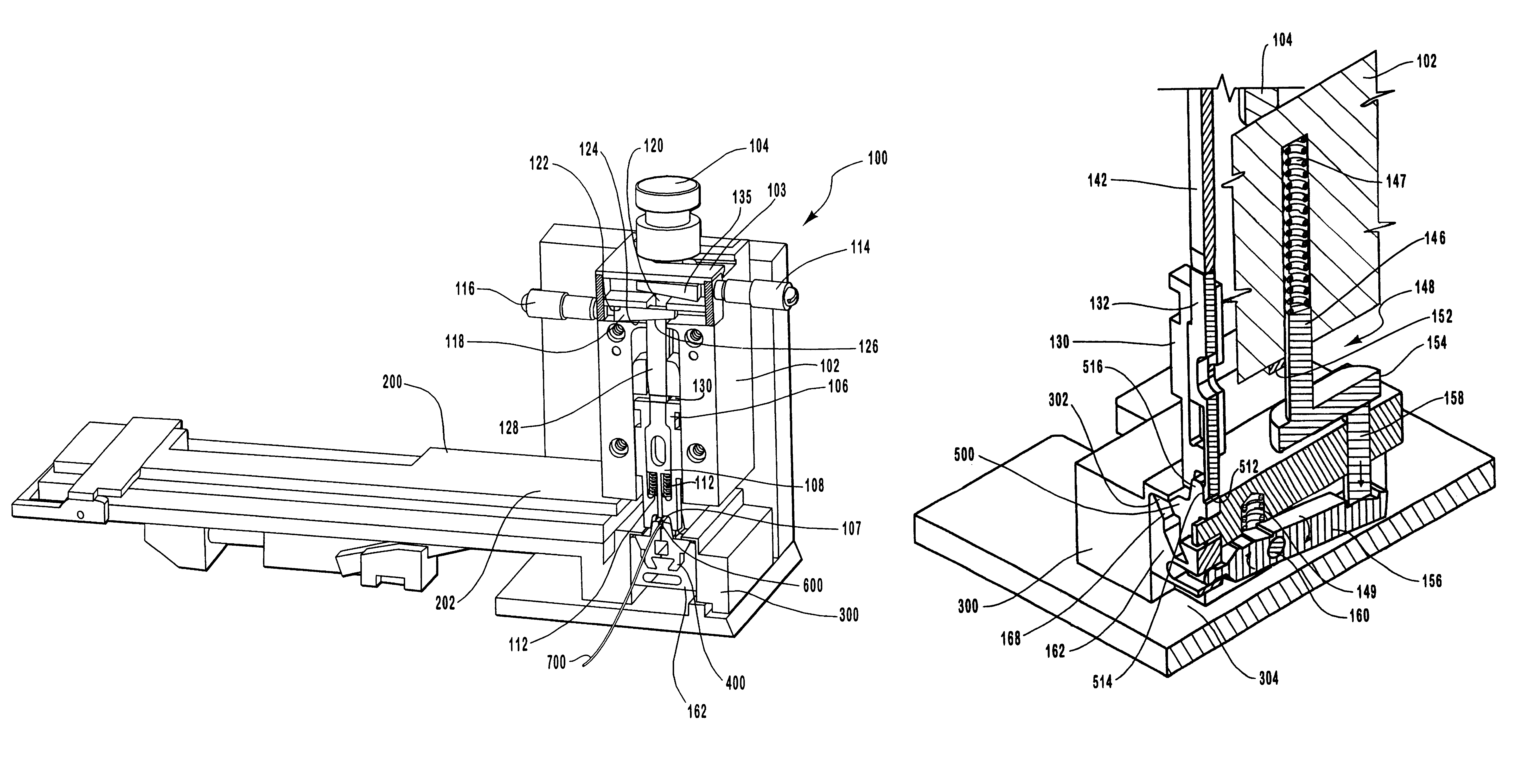
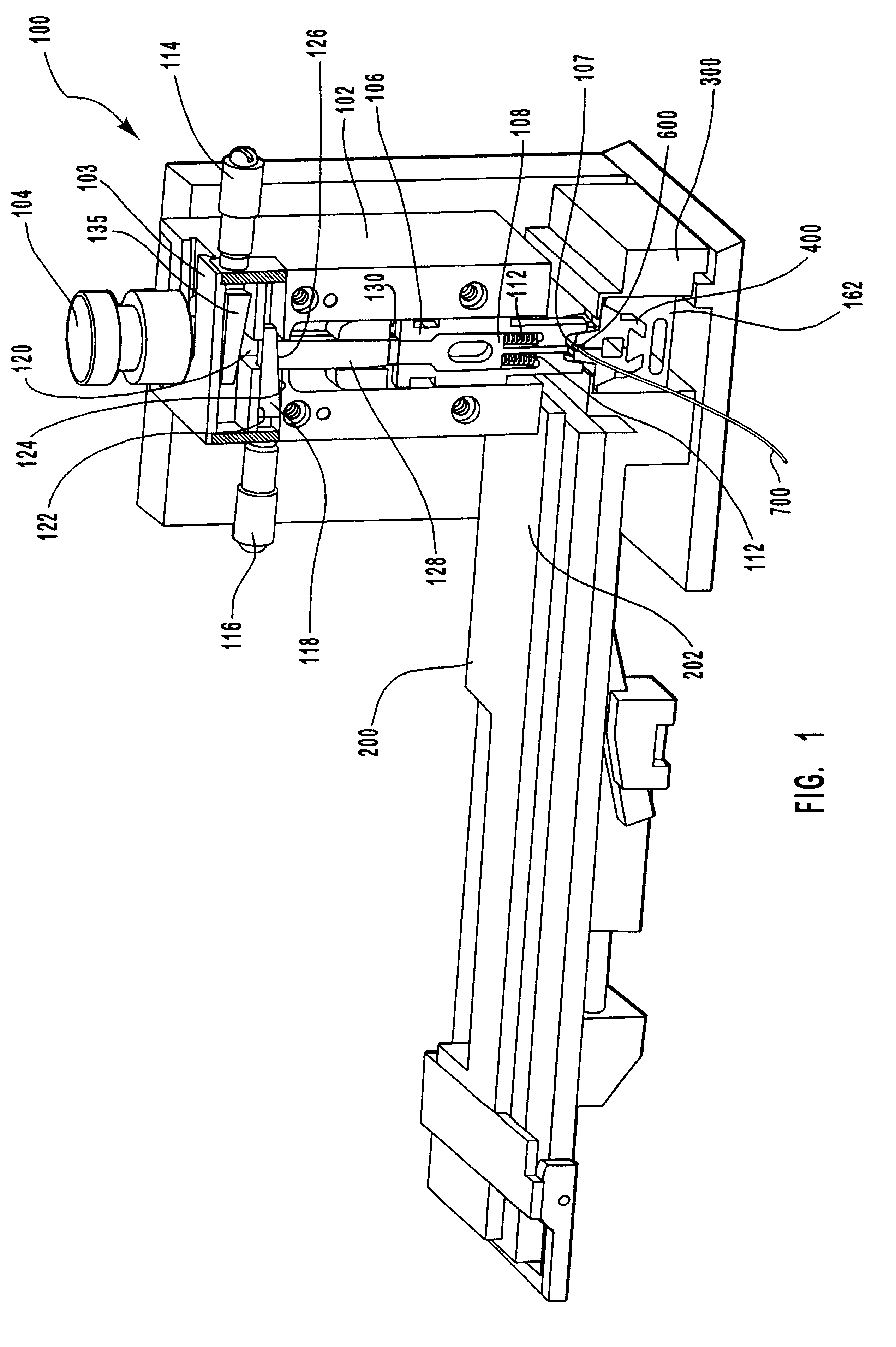
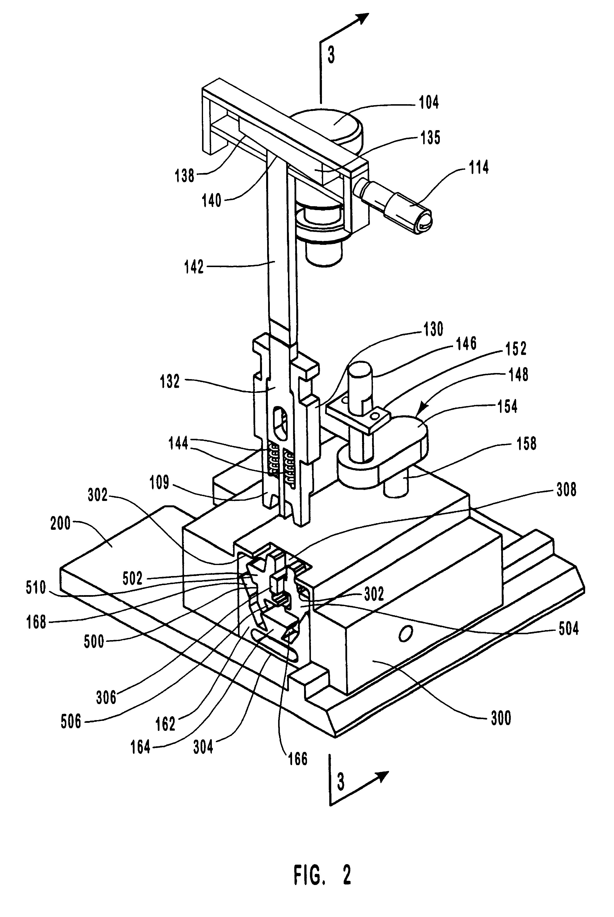
The present invention relates to an applicator die for use in crimping terminals to conducting wires. FIGS. 1 through 5b indicate various embodiments of an applicator die conforming to the teachings of the invention. One embodiment of a crimping applicator is generally indicated in FIG. 1 as 100. Crimping applicator 100 includes an applicator housing 102 and is located at the terminal end 202 of a feed table 200. In one embodiment, applicator housing 102 comprises a steel material or the like. For example, in one embodiment applicator housing 102 is composed of 4140 steel. It will be appreciated that various other steel alloys and other type...


PUM

PropertyMeasurementUnit
angleaaaaaaaaaa
applicator forceaaaaaaaaaa
forceaaaaaaaaaa

Abstract

An applicator die for crimping open loop type terminals to wire leads comprising applicator housing, a plurality of blades and a plurality of housing. An applicator housing is provided which is extended or retracted vertically in response to an applicator force applied thereto. An insulation blade housing with an insulation blade and a core blade housing, with a core blade are movingly disposed inside the applicator housing. Prior to a crimping operation, the applicator housing is retracted and a terminal is moved into position and aligned with the insulation and core blades. A lead wire is also positioned inside the terminal. As the applicator housing descends in response to the applicator force, it pushes the lead wire down into contact with the terminal. A cam lever, acting under the influence of the applicator force, moves a cam vertically, bringing together complementary members of an insulation anvil and a core anvil. As the complementary members of the insulation anvil come together, they pinch the terminal to prevent movement of the terminal during crimping. As the applicator housing descends, the insulation blade housing and core blade housing move from the first position to slidingly embrace the insulation and core anvils. The core blade and insulation blade reach the second or extended position in which they crimp the terminal to a lead wire.

Description

1. The Field of the InventionThe present invention relates generally to a method and apparatus for securely attaching a terminal to a conducting wire. More particularly, embodiments of the present invention relate to an improved applicator die that reliably establishes and maintains the terminal in a desired orientation during processing positively releases the wire / terminal assembly after crimping is complete.2. The Prior State of the ArtA multitude of approaches have been taken to address the problem of connecting an electrical wire to a terminal component. Some approaches focus on a connecting means formed on or in the terminal component. Typically, these connecting means are adapted to receive the bare end of a conducting wire. That is, no special treatment to the end of the wire is required to form the desired electrical connection. One example of such a connecting means is an electrically conductive post about which a wire is wrapped. Typically, the post is threaded so that a ...

Claims


Application Information

Patent Timeline
Patent Type & Authority Patents(United States)
IPC IPC(8): H01R43/058H01R43/04
CPCH01R43/058Y10T29/5149Y10T29/53213Y10T29/53235
Inventor SIGLER, PHILLIP D.DICKAMORE, NATHAN J.THOMAS, KELLY C.
Owner TYCO ELECTRONICS LOGISTICS AG (CH)
Why Eureka
Try Eureka