
Catalyst for hydrogenation treatment and method for hydrogenation treatment of hydrocarbon oil

a hydrogenation treatment and hydrocarbon oil technology, applied in the direction of catalyst activation/preparation, physical/chemical process catalysts, metal/metal-oxide/metal-hydroxide catalysts, etc., can solve the problem of insufficient hydrogenation activity

Inactive Publication Date: 2001-10-23
TONENGENERAL SEKIYU
View PDF19 Cites 34 Cited by
  • Summary
  • Abstract
  • Description
  • Claims
  • Application Information

AI Technical Summary

Benefits of technology

A second object of the present invention is to provide a hydrotreating catalyst which comprises a silica-alumina carrier in which the silica is highly dispersed and which has high desulfurization activity and high denitrogenation activity.
The inventors of the present invention have carried out extensive research regarding the relationship between the desulfurization activity and denitrogenation activity of a hydrotreating catalyst and the physical properties of its carrier. As a result, they found that when silica-alumina comprising a silica layer formed on an alumina surface is used as the carrier, the control of the solid acidity of the hydrotreating catalyst is facilitated, and that the increase in silicon-aluminum bonds and the uniform development of a number of solid acid sites having uniformly acidic properties on the alumina is facilitated; and that as a result both the sulfur compounds and nitrogen compounds in a hydrocarbon oil can be eliminated to a high degree by using a hydrotreating catalyst having as a structural component a silica-alumina carrier which contains a large amount of silica and in which the silica is highly dispersed or a silica-alumina-third component carrier comprising silica, alumina and a third component which has a high pore volume in the relatively small pore diameter regions and whose pore diameter distribution lies within a specific range. It was on the basis of these findings that the present invention was completed.

Problems solved by technology

However, each of the above-described proposed catalysts have the problem that their hydrogenation activity is still not sufficient.

Method used


Image

  • Catalyst for hydrogenation treatment and method for hydrogenation treatment of hydrocarbon oil
  • Catalyst for hydrogenation treatment and method for hydrogenation treatment of hydrocarbon oil
  • Catalyst for hydrogenation treatment and method for hydrogenation treatment of hydrocarbon oil

Examples


example 1

3 liters of pure water were heated to 70.degree. C., and 220 g of sodium aluminate were dissolved therein to prepare an aqueous solution of sodium aluminate having a pH of about 12. Next, a solution of nitric acid was added over 25 minutes to adjust the pH of the solution to the desired pH (8.8-9.2). It was then aged at a temperature of 70.degree. C. for 0.5 hours to prepare an aqueous solution containing a precipitate (gel) of alumina hydrate. Next, an aqueous solution of sodium silicate (No. 3 water glass 49 g, pure water 200 g) was added over 21 minutes, where necessary adding nitric acid solution to adjust and maintain the pH of the obtained aqueous solution to about 9. This was then aged at a temperature of about 70.degree. C. for 0.5 hours to prepare a slurry liquid containing precipitate particles having a silica hydrate deposited on the surface of the alumina hydrate gel. This slurry liquid was then filtered and washed with an aqueous solution of ammonium carbonate until the...

example 2

Catalyst B was prepared in the same way as Example 1 except that nitric acid solution was added over 24 minutes to adjust the pH to the desired pH (8.8-9.2) instead of the step of adding nitric acid solution over 25 minutes to adjust the pH to the desired pH (8.8-9.2), and that an aqueous solution of sodium silicate (No.3 water glass 69 g, pure water 200 g) was added over 20 minutes instead of the step of adding the aqueous solution of sodium silcate (No. 3 water glass 49 g, pure water 200 g) over 21 minutes. The silica content in catalyst B was 16.4% by weight . Hydrotreatment of sample A was carried out using catalyst B under the above-described hydrotreatment conditions to test the desulfurization and denitrogenation activity of catalyst B. The physical properties of catalyst B (chemical composition, specific surface area, pore volume, .sup.29 Si-nuclear magnetic resonance analysis) and the results of the hydrotreatment test are shown in Table 2.

example 3

Catalyst C was prepared in the same way as Example 2 except that an aqueous solution of sodium silicate (No.3 water glass 69 g, pure water 200 g) was added over 33 minutes instead of the step of adding the aqueous solution of sodium silicate (No. 3 water glass 69 g, pure water 200 g) over 20 minutes. The silica content in catalyst C was 16.5% by weight. Next, hydrotreatment of a sample oil was carried out using catalyst C under the above-described hydrotreatment conditions to test the desulfurization and denitrogenation activity of catalyst C. The physical properties of catalyst C (chemical composition, specific surface area, pore volume, .sup.29 Si-nuclear magnetic resonance analysis) and the results of the hydrotreatment test are shown in Table 2.


PUM

PropertyMeasurementUnit
Fractionaaaaaaaaaa
Fractionaaaaaaaaaa
Fractionaaaaaaaaaa

Abstract

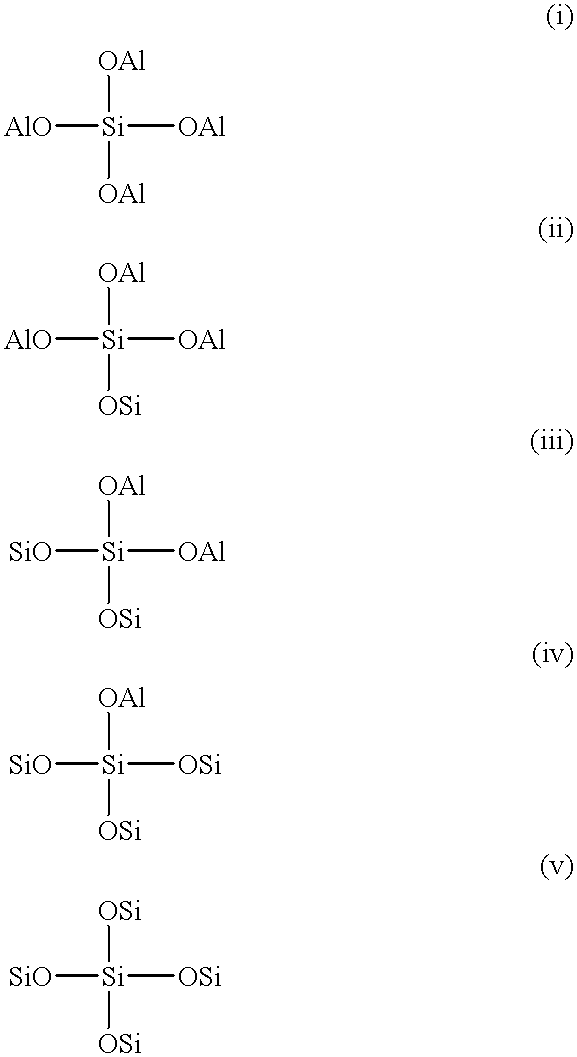
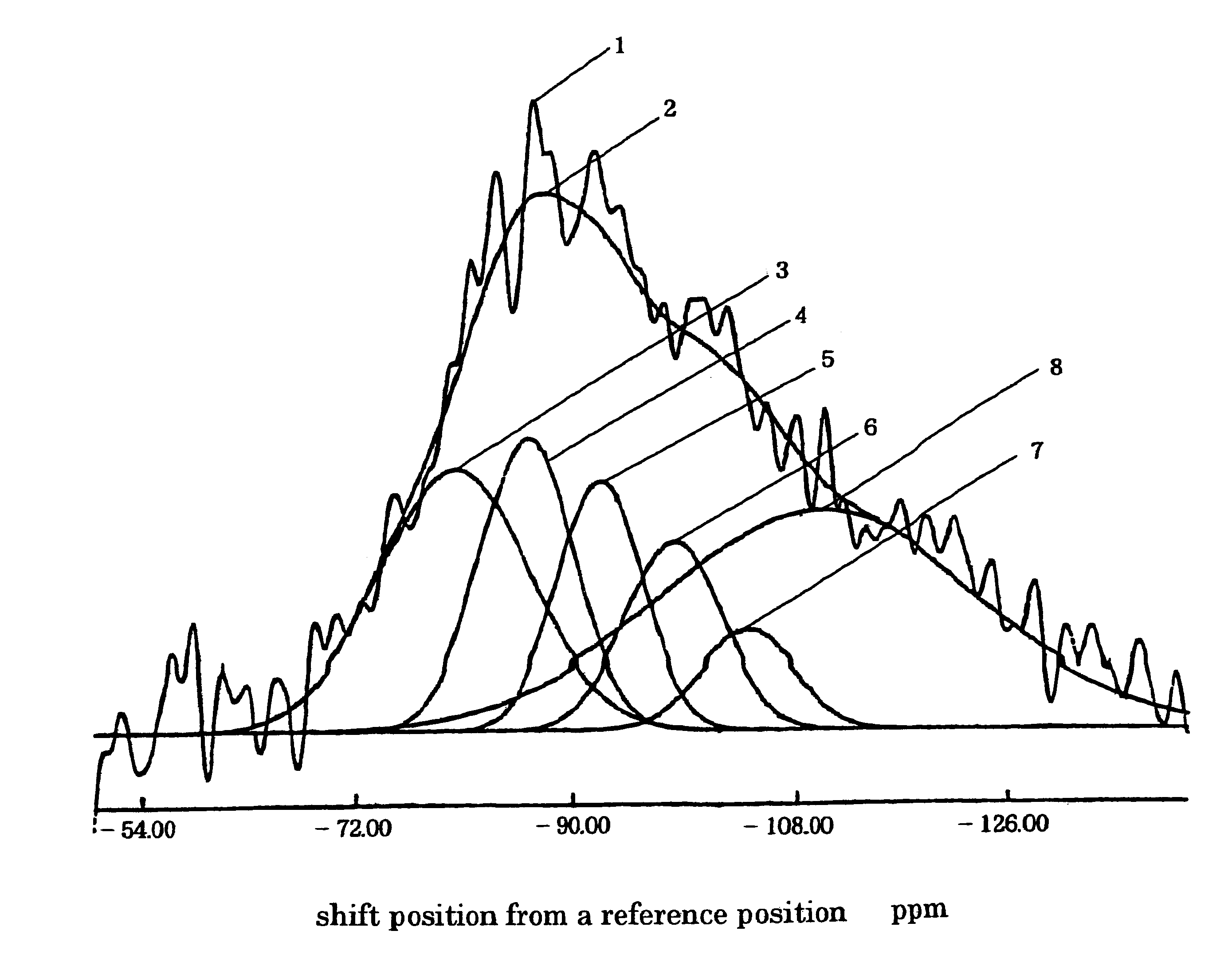
A hydrotreating catalyst having both a high desulfurization activity and a denitrogenation activity and a method of hydrotreating a hydrocarbon oil using the same is provided.A hydrotreatment catalyst comprising a silica-alumina carrier loaded with at least one hydrogenation-active component; wherein (1) the silica content is in the range of 2 to 40% by weight based on the total weight of the carrier; and (2) in the spectrum obtained by nuclear magnetic resonance analysis (29Si-NMR), (i) the area of the peak at -80 ppm is 10% or more of the combined area of all the peaks; and (ii) the combined area of peaks at -80 ppm, -86 ppm and -92 ppm is 20% or more of the combined area of all peaks; a hydrotreating catalyst comprising a silica-alumina carrier containing a specific amount of a third component loaded with at lest one hydrogenation-active metal component and having a specific pore structure; and a method of hydrotreating a hydrocarbon oil comprising contacting a hydrocarbon oil with hydrogen in the presence of said hydrotreating catalyst.

Description

The present invention relates to a hydrotreating catalyst and to a method of hydrotreating hydrocarbon oils using the same. More specifically, the present invention relates to a hydrotreating catalyst comprising a silica-alumina catalyst carrier in which the silica is highly dispersed or a silica-alumina carrier having a specific pore structure loaded with at least one type of hydrogenation-active metal component, and in particular, to one having a high degree of silica dispersion specified by nuclear magnetic resonance analysis; and to a method of hydrotreating hydrocarbon oils such as hydrodesulfurization, hydrodenitrogenation, hydrocracking, hydrodearomatization, hydroisomerization, and hydrofining using the same.PRIOR ARTTo date, there have been developed various hydrotreating catalysts for hydrotreating hydrocarbon oils in the process of producing petroleum products comprising a refractory inorganic oxide carrier such as alumina, silica-alumina, magnesia or zirconia loaded with...

Claims


Application Information

Patent Timeline
IPC IPC(8): B01J21/00B01J21/02B01J21/12B01J23/883B01J23/882B01J23/76B01J35/10B01J35/00C10G45/02C10G45/08B01J21/10B01J23/85B01J37/02B01J37/00B01J37/03B01J23/88
CPCB01J21/02B01J21/12B01J23/88B01J23/882B01J23/883B01J35/10C10G45/08B01J21/10B01J23/85B01J35/002B01J35/1019B01J35/108B01J37/0205B01J37/03B01J35/30B01J35/60B01J35/66B01J35/615
Inventor HAYASHI, FUMITAKAKAMO, AKIRATOSHIMA, HIROSHI
Owner TONENGENERAL SEKIYU
Learn More