Process and device for gasification of waste

a gasification device and waste technology, applied in the direction of gasification of molten salts/metals, combustion types, manufacturing converters, etc., can solve the problems of high cost of environmental neutral incineration of waste products, the cost of shipping waste from the point of origin to the incineration facility to become a non-negligible part of the overall cost, and the effect of reducing the viscosity of slag

Inactive Publication Date: 2001-11-06
LINDE KCA DRESDEN
View PDF27 Cites 23 Cited by
  • Summary
  • Abstract
  • Description
  • Claims
  • Application Information

AI Technical Summary

Benefits of technology

An important parameter of the operation of the slag bath gasifier is the viscosity of the slag. Silicic acid is formed by SiO.sub.4 tetrahedra whose centers contain a Si atom surrounded by four O atoms. Because of common oxygen atoms, these tetrahedra form space lattices which also remain in the liquid state as coherent complexes. The limited mobility of these large structures ensures high viscosity. The Al.sup.3+ cations can substitute the Si.sup.4+ cations and form AlO.su

Problems solved by technology

As a result, the technical costs involved in the environmentally neutral incineration of waste products are so high that only units with large throughput rates are able to wo

Method used


Image

  • Process and device for gasification of waste
  • Process and device for gasification of waste
  • Process and device for gasification of waste

Examples


example 1

Refuse Incineration

Table 1 shows the composition of a standard refuse according to the Land Environmental Department of North Rhine-Westphalia.

The pre-treatment of the refuse is limited to the coarse crushing of the feed material to a grain size of less than 40 mm. Iron may also be removed by magnetic separation.

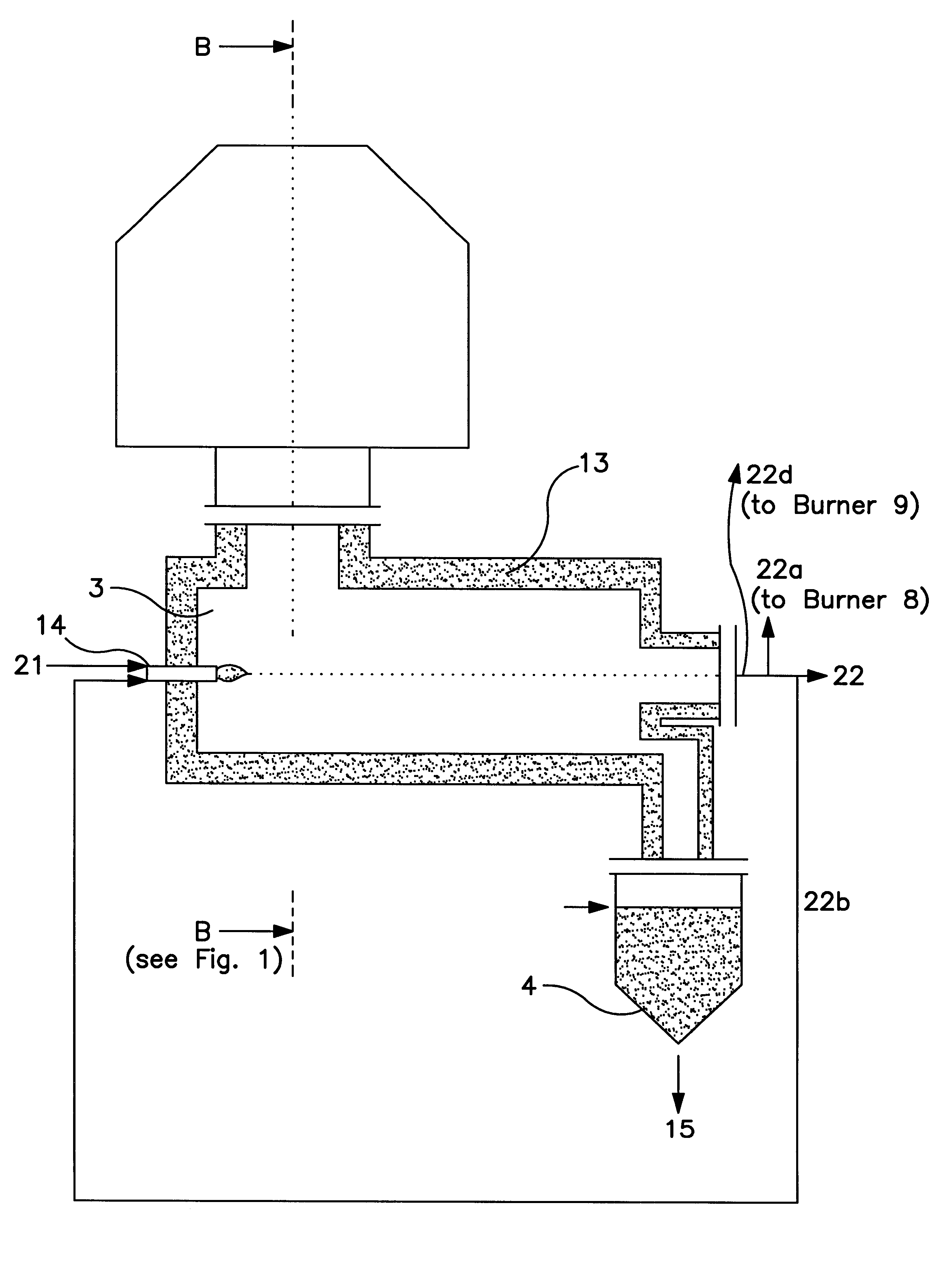
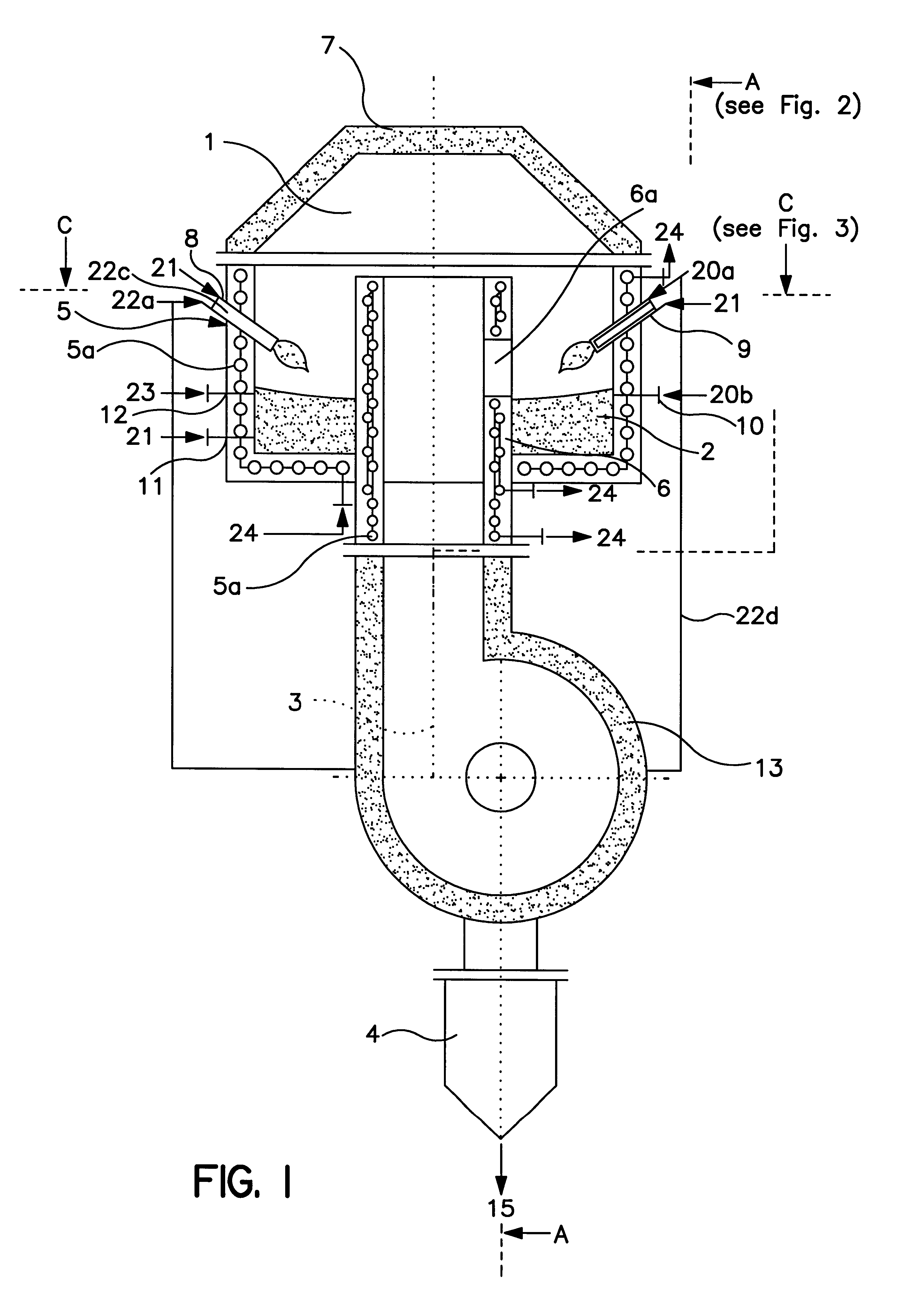
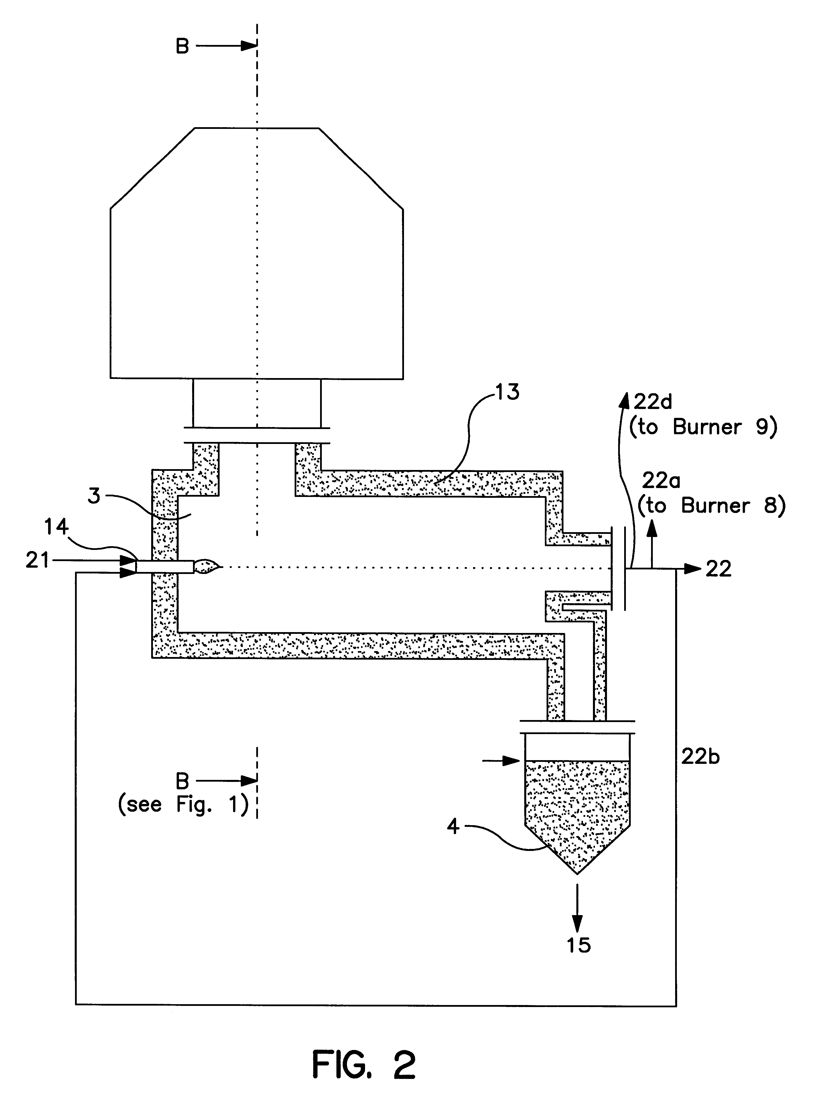
The 0-5 mm grain fraction is fed into the gasification space via the solids burners, while the 5-40 mm grain fraction is fed in via a nozzle by means of feed screws.

As Table 3 indicates, 357 m.sup.3.sub.i.N. [i.N.=in normal state] of oxygen (96 vol-% of O.sub.2) is used for the autothermal gasification of 1.0 ton of refuse.

Owing to the moisture content of the feed material, the cracked gas that is obtained has a large proportion of vapor. In addition, the cracked gas has large CO and H.sub.2 contents, so that sufficient energy reserves are available to cover any higher heat losses that may occur.

The ash from the refuse has high contents of SiO.sub.2 and Al.sub.2 O.sub.3, whi...

example 2

Gasification of Old PVC

An advantageous application of the slag bath gasifier according to the invention is the gasification of waste PVC since, in addition to refuse disposal, the HCl contained in the PVC can be recovered and used as HCl gas in oxychlorination and ultimately to produce PVC again.

Table 2 presents the composition of a PVC-containing waste mixture.

In addition to screening with corresponding crushing of the waste PVC to a grain size of d<40 mm and the magnetic separator for removing iron, an additional air separator (zigzag separator) should be provided for the pre-treatment process. In the latter separator, heavy non-ferrous metals are separated which, in the slag bath, are converted into metal chloride for the most part and thus would reduce the HCl yield. By contrast, the silicates and light metals (Al, Mg) are desired slag formers.

The option of using relatively coarse-grain feed material is especially economical in the case of PVC because this means that crushing in...


PUM

PropertyMeasurementUnit
Angleaaaaaaaaaa
Diameteraaaaaaaaaa
Diameteraaaaaaaaaa

Abstract

Gasification of waste is performed in a gasifier having a gasification space (1) and a liquid rotating slag bath (2). The slag bath (2) is preferably caused to rotate by tangentially injecting gasification medium and/or at least a portion of the waste via a burner toward the surface of the slag bath. Waste with a diameter of to 5 mm is preferably introduced into gasifier (1) above the slag bath (2), while larger waste is preferably introduced directly into the slag bath. Slag is a removed, together with cracked gas accumulated during gasification through the floor of the gasifier via a slag drain having a lateral opening which protrudes above the slag bath.

Description

SUMMARY OF INVENTIONIt may be that in the future, waste with organic admixtures will no longer be disposed of in landfills. Therefore, to an increasing extent, waste is being subjected to thermal disposal in the form of burning (refuse incineration) or gasification.For refuse incineration there are technically sophisticated processes which, with maximum efficiency for the generation of thermal and electrical energy, produce environmentally neutral by-products. This requires incineration parameters that ensure the production of slags that are highly resistant to having the heavy metals contained therein being leached out by water. It is also necessary to ensure that dust, nitrogen oxides, and dioxins / furans are extensively scrubbed out of the flue gases. Filter dust and processing water that are produced also need to be converted into environmentally neutral products at a reasonable cost. As a result, the technical costs involved in the environmentally neutral incineration of waste p...

Claims


Application Information

Patent Timeline
IPC IPC(8): C10J3/00C10J3/57B09B3/00F23G5/027F23G5/14F23G5/00F23J1/00
CPCC10J3/57C10K1/026C10J2300/0946C10J2300/0993C10J2300/0996C10J2300/1223C10J2300/1634C10J2200/152Y10S266/90Y10S48/04Y10S48/02Y10S48/01
Inventor MARSCHNER, SIEGMARHALANG, SVEN
Owner LINDE KCA DRESDEN
Why Eureka
Try Eureka