Microelectromechanical systems (MEMS)-type high-capacity inertial-switching device

Inactive Publication Date: 2001-11-13
UNITED STATES OF AMERICA THE AS REPRESENTED BY THE SEC OF THE ARMY
View PDF4 Cites 81 Cited by
  • Summary
  • Abstract
  • Description
  • Claims
  • Application Information

AI Technical Summary

Benefits of technology

The G-switching devices of the invention can be used in various military applications by providing a mechanically-enabled, latching mechanical inertial switch (G-switch) device; an electromechanically enabled latching mechanical G-switch device; a miniature unpowered inertial t-zero or power switch device to enable electronic circuits within either gun-launched or tube-launched based weapons or instrumentation packages (for example, flight recor

Problems solved by technology

However, fabrication of such devices is costly since such devices are constructed from extremely precision components, often requiring time-consuming component sorting, thus limiting their use.
Finally, such devices also include arrangements wherein mechanical sequential interlocks control motion of a slider/rotor mechanism such that out-of-sequence actuation of the interlocks leads to a fail-safe condition.
Overall, prior art arrangements are such that mechanical fuze S&A devices comprise complicated, three-dimensional assemblies of piece-parts working t

Method used


Image

  • Microelectromechanical systems (MEMS)-type high-capacity inertial-switching device
  • Microelectromechanical systems (MEMS)-type high-capacity inertial-switching device
  • Microelectromechanical systems (MEMS)-type high-capacity inertial-switching device

Examples


first embodiment

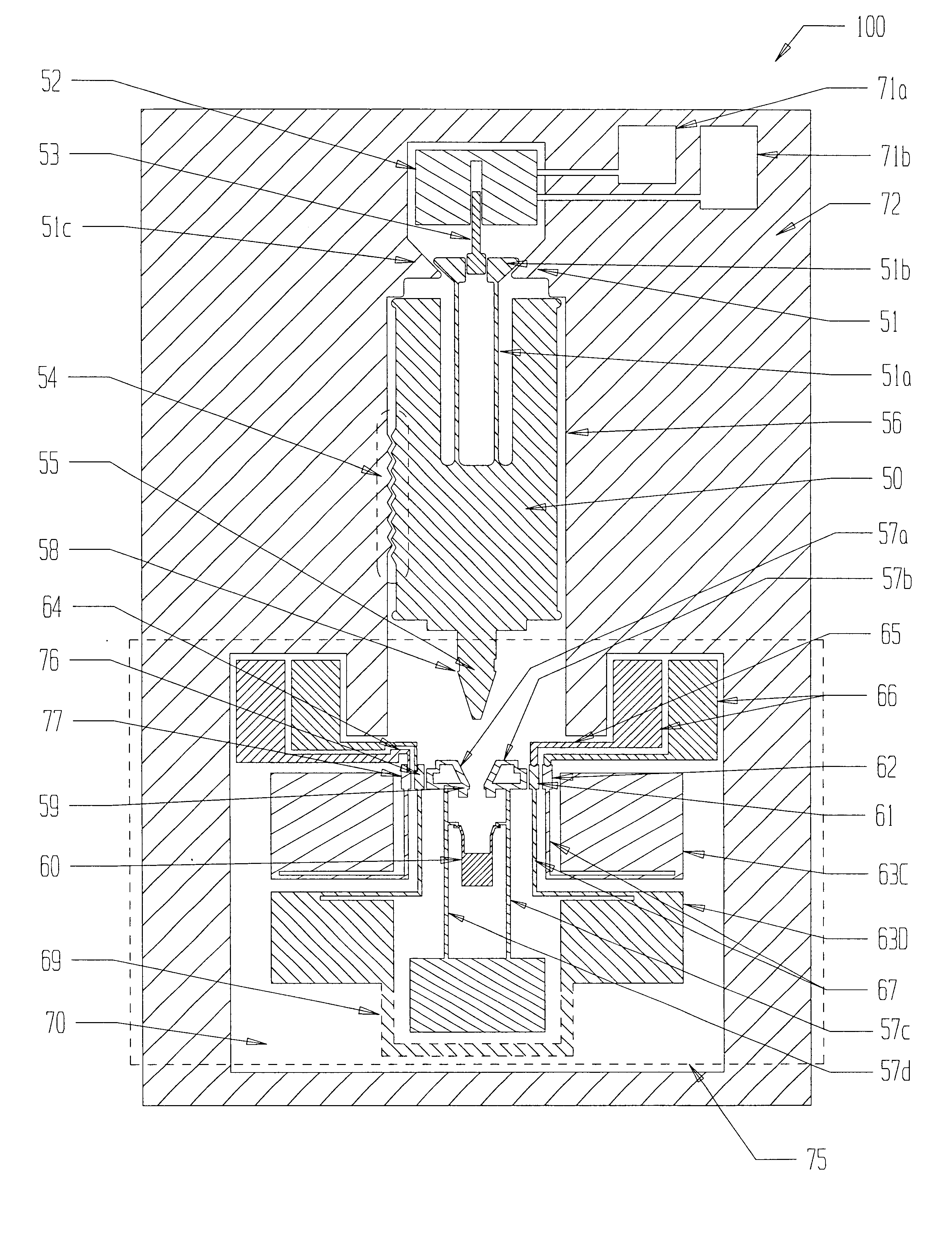
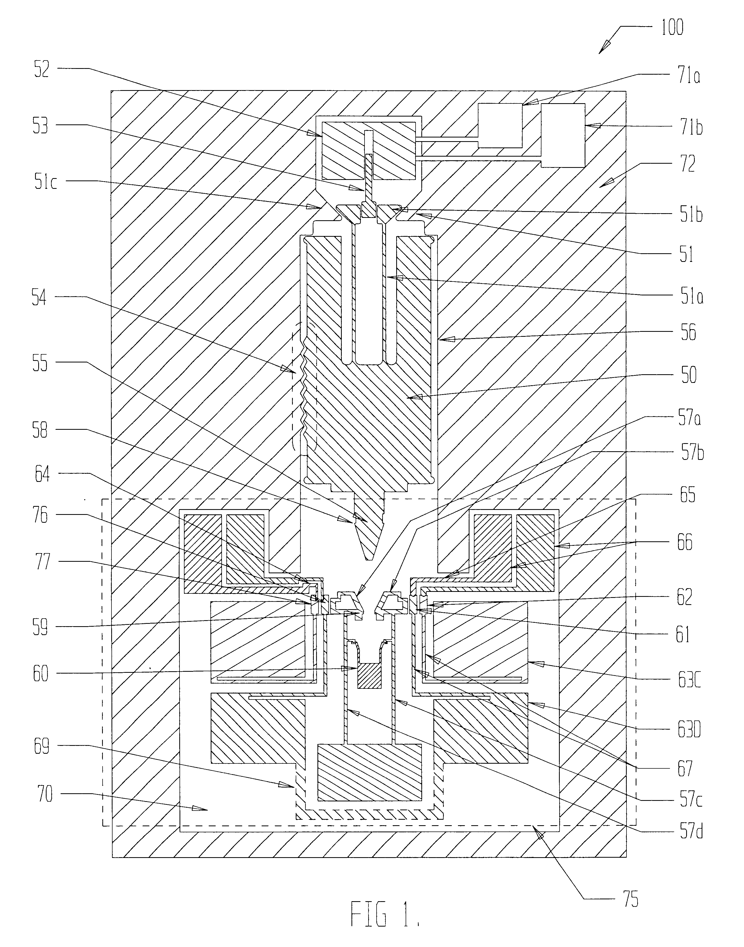
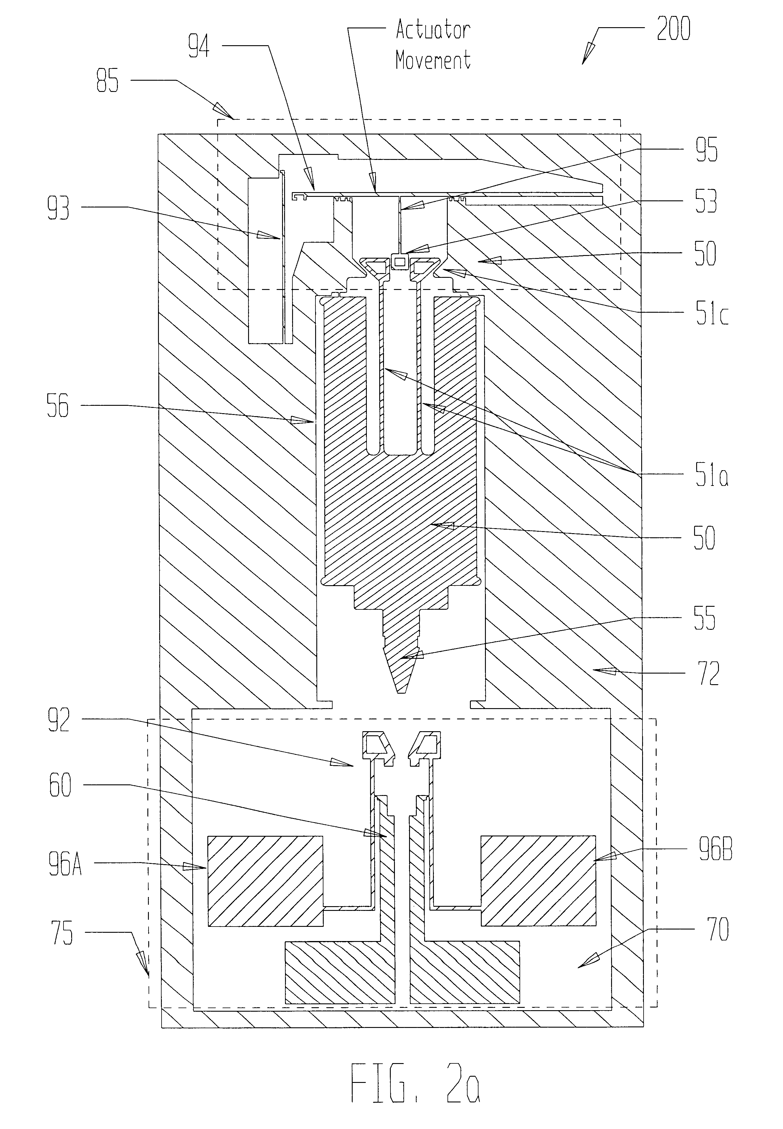
: Referring now to FIG. 1, the invention is shown in a sectional plan view of a MEMS-type unpowered G-switch device 100 with electromechanical enable capability. This switching device comprises an actuator component 52 that provides enablement of the switch device 100, a shuttle member 50, an anchor assembly 51 that includes the following members of anchor legs 51a, anchor feet 51b that are attached to the shuttle member and are shaped to bear laterally against constriction members 51c; and one of several designs of a switching assembly 75. Each constriction member 51c has a cam face that is attached to the substrate 70 and forming part of a raised structural upper section of the MEMS-type device and shown as just one of many "land" structures 72 that form this raised section. After the anchor feet are unpinned by upward movement of a linchpin 53 and out from between the feet 51b, the anchor feet can slide past these constriction members allowing the shuttle 50 to be pulled downward...

second embodiment

the invention can also be used as a threshold G-switching device. In such a design, the linchpin 53 and lift arm assembly 85 are omitted, wherein the anchor foot assembly 51 holds the shuttle 50 in an initial configuration until upward acceleration is applied sufficient enough to pull the anchor feet 51b through the constriction 51c. The accelerating threshold at which the anchor feet pull free is a function of friction, mass of the shuttle, and design of the anchor foot assembly 51.

SWITCHING ASSEMBLIES: Various designs of the switching assembly 75 can be used in either embodiment of the invention. As shown in FIG. 1 (for example) the contact hammers 57a and 57b interact with the shuttle head 55 to close the switch assembly by acting upon the anvil pair 61 and 62. The switching assembly 75 can be a latching single-throw switch of a type being either a normally-open, double pole, single-throw switch or a normally-open, single pole, single-throw switch.

Referring now to FIGS. 3 and 4, ...


PUM


Abstract

Various ultra-miniature, monolithic inertial switching (G-switch) devices used in safety and arming (S&A) devices for projected munitions, which operate in accordance with a shuttle member (50), which effectuates current switching of around an ampere of current when subjected to a threshold inertial loading (for example, an impact or gun launch of a projection munition). The embodiments of the invention can be a passive threshold G-switch with or without switch enable and arming capability. The embodiments (100, 200) of the invention use either mechanical or electromechanical switch enable functioning and can optionally include a shuttle time-delay feature (54). Both embodiments can incorporate various designs for a switching assembly (75) such as latching single-throw switch having the configurations of either a normally-open, double pole, single-throw switch or a normally-open, single pole, single-throw switch, wherein switch closing occurs when the shuttle member (50) experiences inertial loading and penetrates the switching assembly (75).

Description

The present invention relates generally to microelectromechanical systems (MEMS)-type devices and, more particularly, to microelectromechanical safety-and-arming (S&A) devices used in fuzing applications.DESCRIPTION OF THE PRIOR ARTExplosive projectiles, such as mortar shells, artillery shells and other similar projectiles, normally have an S&A device, which operates to permit detonation of the explosive only after the projectile has been fired or launched. Thus, mechanical arming delay mechanisms for such projectiles or explosives are well known in the art.For example, three-dimensional rotary or linear zigzag delay (that is, inertial delay) devices on the scale of millimeters or centimeters, fashioned by precision machining, casting, sintering or other such "macro" means, have previously been used to provide a mechanical delay before closing a switch, or removing a lock on a detonator slider in a fuze S&A device. Such devices are disclosed, by way of example, in U.S. Pat. Nos. 4,2...

Claims


Application Information

Patent Timeline
IPC IPC(8): F42C19/00F42C19/06H01H1/00H01H35/14
CPCF42C19/06H01H1/0036H01H35/14H01H2001/0047
Inventor ROBINSON, CHARLES H.
Owner UNITED STATES OF AMERICA THE AS REPRESENTED BY THE SEC OF THE ARMY
Why Eureka
Try Eureka