Electro-pyrotechnic initiator

a technology of pyrotechnic initiators and initiators, which is applied in the direction of electric fuzes, weapons, ammunition fuzes, etc., can solve the problems of large variation in resistance, large variability in resistance, and prior art initiators that require a relatively large amount of energy to initiate autoignition or become more costly with less reliability, etc., to achieve the effect of small size and lower cos

Inactive Publication Date: 2001-12-04
VISHAY INTERTECHNOLOGY INC
View PDF29 Cites 61 Cited by
  • Summary
  • Abstract
  • Description
  • Claims
  • Application Information

AI Technical Summary

Benefits of technology

Another feature of the present invention is an electro-pyrotechnic initiator that can be fired using a low capacitance ceramic capacitor of smaller size and lower cost.

Problems solved by technology

These types of initiators, which are used in variety of settings such as military and air bag applications, suffer from a variety of deficiencies.
For example, prior art initiators either require a relatively large amount of energy to initiate autoignition or become more costly with less reliability when reduced to low energy activation levels.
In one such prior art device, known as bridgewire technology, reducing the energy level requires using an electrically conductive wire of such narrow diameter that variations in contact point result in large variations in resistance; parts are more difficult and costly to produce; and the wire elements are more susceptive to damage, thereby reducing reliability.
In addition, prior art initiators often utilize multiple levels of successively more sensitive energetic or pyrotechnic materials, adding to the overall cost of the initiator.
Finally, variance in the resistivity of the resistive element from the beginning to the end of the manufacturing process leads to unreliability in prior art initiators.
The grinding of the header adds cost to the electro-pyrotechnic initiator.
In addition, the bridgewire technology requires costly equipment to orient the product to achieve the precise welding positions that are necessary to get the correct resistance value.
Furthermore, the bridgewire technology has two zones of potential electrostatic discharge that could either produce an electric arc or make an electrical contact which would reduce the effective resistance of the bridgewire, making it responsive to an activation energy lower than the designed autoignition energy which would result in accidental firing of the device at electrostatic discharge energies lower than their designed safety levels.
The accidental firing of the initiator would expose vehicle occupants or mechanics to unnecessary danger.
Occupant safety systems on contemporary vehicles require relatively high capacitance, which adds to both size and cost.
Lower cost ceramic capacitors do not have the capability to store the relatively high energy required to activate contemporary systems.
Adding an explosive varnish to the resistive element increases the cost of the initiator.
In addition, the initiator disclosed in U.S. Pat. No. 5,544,585 requires a relatively large amount of energy in order to ignite the explosive varnish.
To fire this initiator using a capacitor, a relatively expensive electrolytic capacitor must be used in order to obtain the capacitance needed to store enough energy.

Method used


Image

  • Electro-pyrotechnic initiator
  • Electro-pyrotechnic initiator
  • Electro-pyrotechnic initiator

Examples


second embodiment

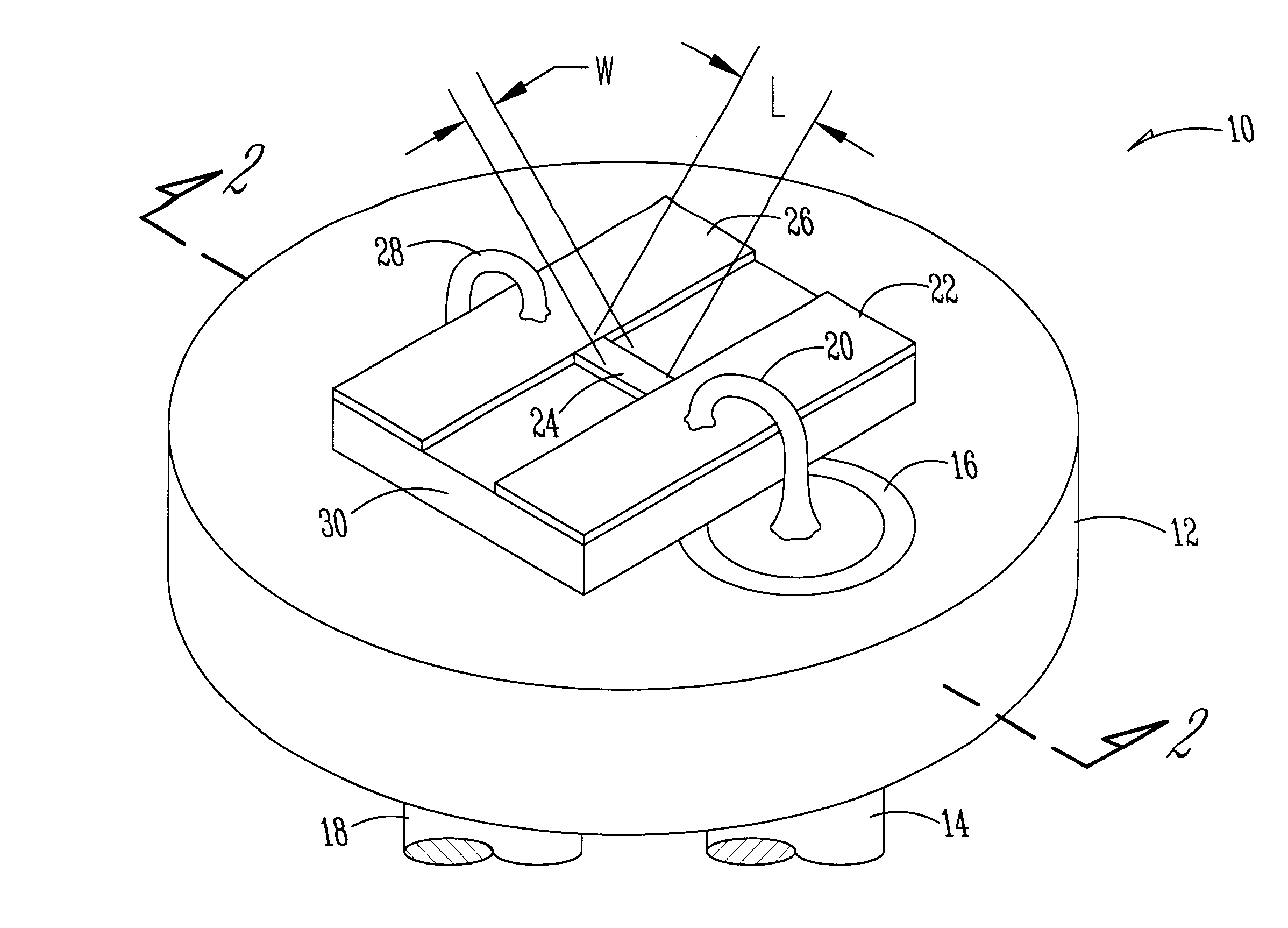
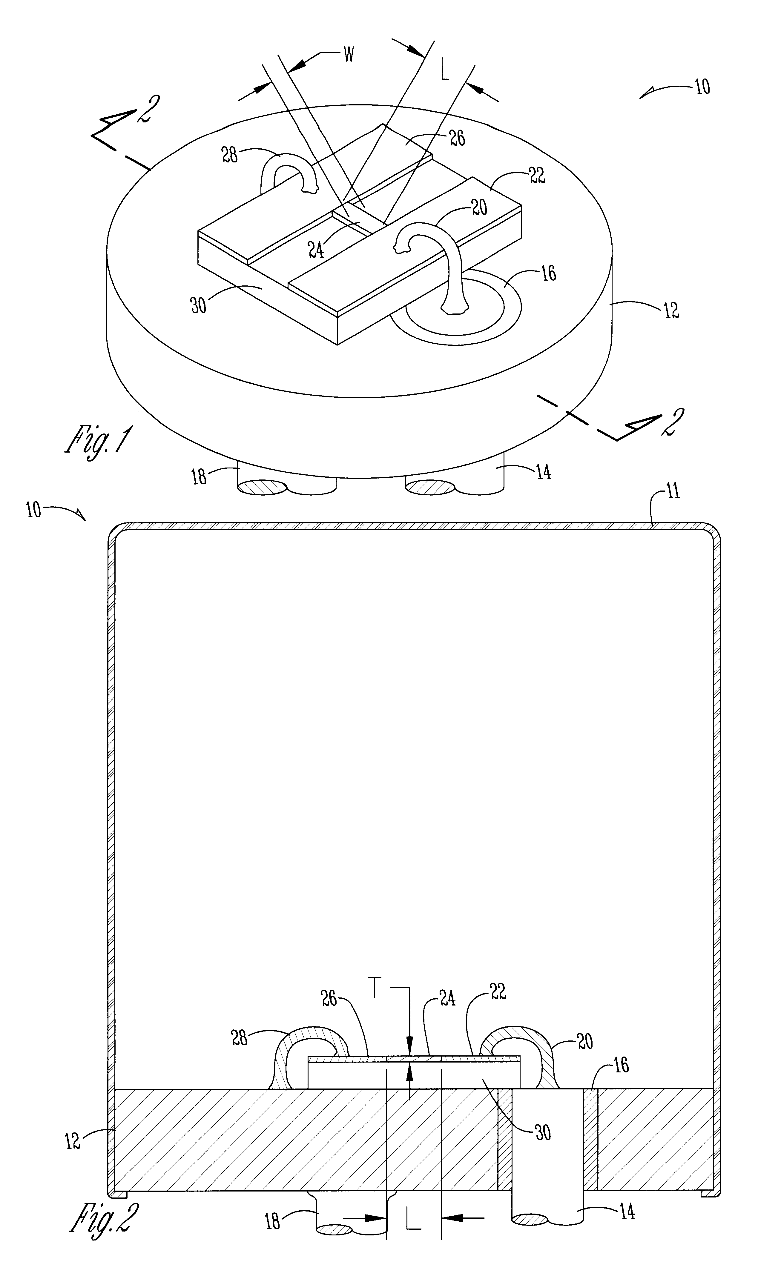
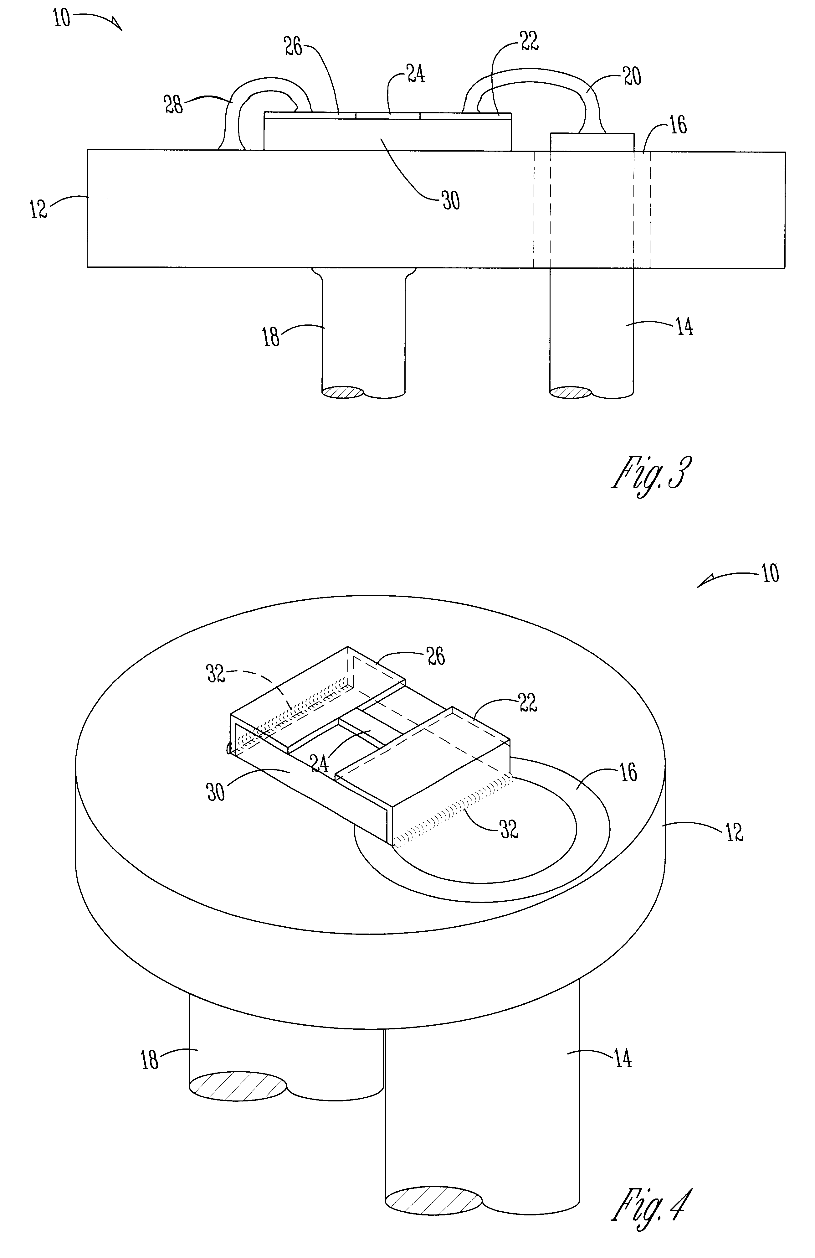
the present invention is shown in FIG. 3. The only difference between the device in FIG. 3 and that of FIGS. 1-2 is that the first pin 14 extends above the header 12. In the bridgewire technique of the prior art, the top of pin 14 and the surface of glass insulator 16 had to be co-planar with the header 12. The present invention eliminates the need to make the top of the pin and the glass insulator co-planar with the header, greatly reducing the cost to make the electro-pyrotechnic initiator.

FIG. 4 is also very similar to FIGS. 1-3. The only difference is that rather than a standard wire bond, solder 32 is used to electrically connect the bonding pads to the first pin 14 and to the header 12. FIG. 4 shows that the surface mounted foil-resistive strip 24 can be mounted directly to a header 12 that may presently be used for a bridgewire element. There is no retooling required.

FIG. 5 shows a fourth embodiment according to the present invention. The electro-pyrotechnic initiator 110 of ...

fifth embodiment

A fifth embodiment according to the present invention is shown in FIG. 6. The electro-pyrotechnic initiator 210 has a header 212. A first pin 214 runs through the header. The first pin 214 is the electrically isolated from the header 212 by a glass collar similar to item 16 in FIG. 1. The supporting substrate 216 for resistive strip 222 and its terminating end pads 218 and 224 is an insulating material such as epoxy-glass or polyimid. The first pin 214 is electrically coupled to a first solder pad or conduction area 218 by a fillet of solder 220. The first solder pad is electrically connected to the activating resistive strip 222. The resistive strip 222 is a foil resistor. The resistive strip 222 is electrically connected to a second solder pad 224. The second solder pad 224 is electrically connected to a second pin 228 through a fillet of solder 220. The second pin 228 is also electrically isolated from the header 112 by a collar of insulating glass similar to item 16 in FIG. 1. I...


PUM


Abstract

An device for use in an electro-pyrotechnic initiator comprises a header, a foil resistive strip, a substrate, and a current source. The substrate is mounted on the header. The foil resistive strip is mounted on the substrate. The energy source is connected to the resistive strip. When current flows through the resistive strip, the resistive strip generates enough heat to spark autoignition of a pyrotechnic material. The pyrotechnic material is in direct contact with the resistive strip. For an energy input of up to 115 microjoules, the resistive strip can cause autoignition in less than 25 microseconds. In a second embodiment, an electro-pyrotechnic initiator for use in a "smart" airbag system comprises a header, a foil resistive strip, a substrate, a current source connected to the resistive strip, and a control circuit. The control circuit is designed such that it will cause current to flow through the resistive strip when the circuit receives an appropriate signal. A ceramic capacitor can be used as an energy source for the resistive strip.

Description

1. Field of the InventionThe present invention relates to an electro-pyrotechnic initiator. More specifically, the present invention relates to a device that utilizes a foil resistive element to generate heat and utilizes the heat produced to achieve autoignition temperature in an energetic or pyrotechnic material.2. Problems in the ArtElectro-pyrotechnic initiators are known in the art. These types of initiators, which are used in variety of settings such as military and air bag applications, suffer from a variety of deficiencies. For example, prior art initiators either require a relatively large amount of energy to initiate autoignition or become more costly with less reliability when reduced to low energy activation levels. In this specification, autoignition temperature is the temperature at which a sample either deflagrates or detonates (in an energetic material), or rapidly combusts or decomposes to release gas, heat, or light (in a pyrotechnic material), under contact heatin...

Claims


Application Information

Patent Timeline
Patent Type & Authority Patents(United States)
IPC IPC(8): F42B3/12F42B3/00
CPCF42B3/124F42B3/13
Inventor TROIANELLO, ANTHONY E.
Owner VISHAY INTERTECHNOLOGY INC
Why Eureka
Try Eureka