Detection of phase defects on photomasks by differential imaging

a technology of differential imaging and phase defects, applied in the field of detection of phase defects on photomasks by differential imaging, can solve the problems of phase difference producing a destructive interference null between the two shapes, less adept at detecting transparent phase defects, and state-of-the-art inspection systems

Inactive Publication Date: 2001-12-04
IBM CORP
View PDF3 Cites 39 Cited by
  • Summary
  • Abstract
  • Description
  • Claims
  • Application Information

AI Technical Summary

Benefits of technology

FIGS. 8a-8b are simulated images using standard industry practice for the properly fabricated shapes and for the missing shifter pattern depicted in FIGS. 7a-7b respectively, wherein small differences between the two images indicate that prior art inspection methods are insufficient to identify the absence of the phase-shifted pattern on a given shape;

Problems solved by technology

If two clear shapes which transmit light of opposite phases (180.degree. phase difference) are placed in close proximity to one another, the phase difference will produce a destructive interference null between the two shapes.
Such defects may result from, but are not limited to, partial blockage of the chrome etch between the fabrication steps shown in FIGS. 1b-1c, or mask contamination by opaque, foreign material (FM) prior to mask inspection.
State-of-the-art inspection systems, however, are less adept at detecting transparent phase defects with small phase (relative to 0.degree. or 180.degree.) and / or size, and yet such defects can also have an anomalous effect on the printed image on the wafer. FIG. 4 indicates a possible phase defect on a standard COG mask comprising the small region of the quartz substrate (230) in between desired chrome shapes (210) and (220) which has been accidentally etched during fabrication or repair.
The small difference between the two images indicates that inspection methods practiced today are not sufficient for detecting the absence of the phase shifted pattern on shape (540).

Method used


Image

  • Detection of phase defects on photomasks by differential imaging
  • Detection of phase defects on photomasks by differential imaging
  • Detection of phase defects on photomasks by differential imaging

Examples


Embodiment Construction

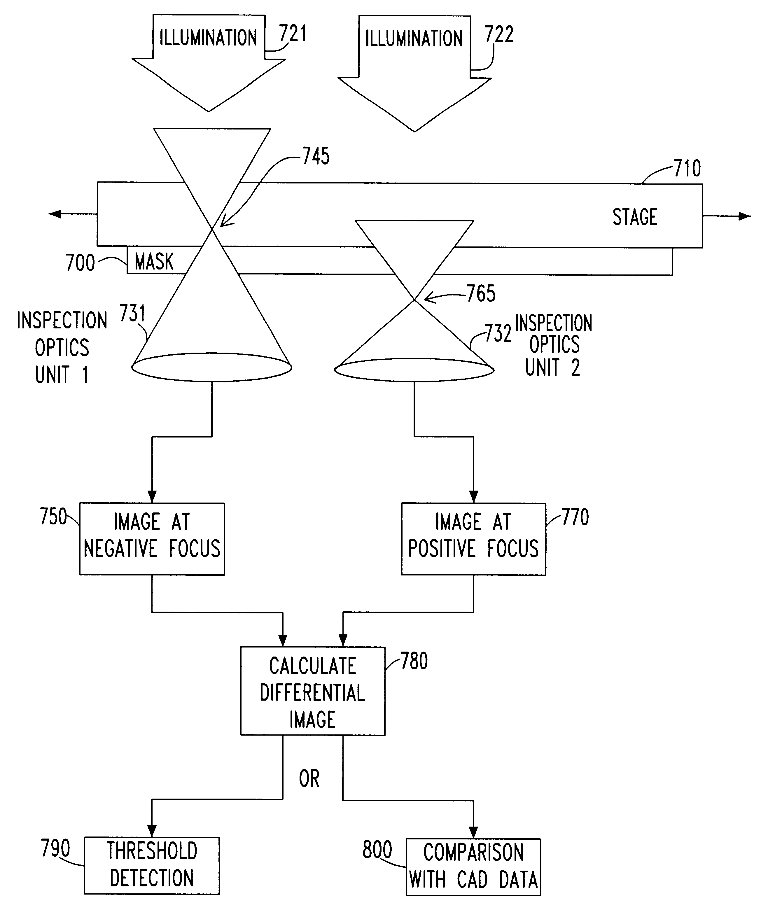
The invention described herein for detecting phase defects on a mask takes advantage of asymmetric imaging characteristics that occur as a function of focal position when the phase of a feature (defined hereinafter as a desired shape on the mask) or defect (defined hereinafter as an undesired shape on the mask) does not equal to 0.degree. or 180.degree. or some multiple thereof as defined in equation (1), wherein .lambda. is the optical inspection wavelength. In the preferred embodiment of this invention a fabricated mask (either COG or PSM as described in the background section) which may contain phase defects or features is illuminated by light at the inspection wavelength and the transmitted (or reflected) image of the mask is measured by an optical lens or objective at two focus positions that are equally spaced about the optimum focus, also referred to as "best" focus (i.e., at a focal position which produces the maximum image contrast of the mask patterns) in a positive and ne...


PUM

PropertyMeasurementUnit
wavelengthaaaaaaaaaa
phase defectsaaaaaaaaaa
wavelengthaaaaaaaaaa

Abstract

A method for detecting phase features or phase defects on photomasks for optical lithography is described. The asymmetric imaging behavior through focus of defects or features with a phase other than 0° or 180° is used to distinguish them from other features on the mask. The mask is inspected at equally spaced positions about an optimum focus in both positive and negative directions. The images are subtracted from one another to produce a differential image of the mask. While opaque features as well as transmitting features at 0° and 180° behave identically at positive and negative defocus, thus leading to a zero-valued differential image, the focus asymmetry of phase defects and features produces a non-zero differential image from which these phase defects and features can be located. By comparing the locations on the mask for which a non-zero differential image is obtained with the designed data for the mask, the phase defects can be sorted from the phase features and the absence of phase features can be detected. Additional image processing can be applied to verify the integrity of the phase features. The differential image inspection technique can be implemented on existing optical inspection tools by employing a two-pass inspection performed at positive and negative defocus in sequence. In addition, a new apparatus with parallel inspection optics is described for inspecting the mask at positive and negative focus simultaneously.

Description

This invention relates, generally, to photolithography, and more particularly, to a method and apparatus for detecting phase defects and other phase features on a photomask using differential imaging.In the photolithography step of integrated circuit manufacturing, a template containing a designed set of clear and dark shapes, referred to as the mask or reticle, is repeatedly printed on the surface of a silicon wafer. This process is achieved by way of optical imaging at an image size resolution defined primarily by the wavelength (.lambda.), numerical aperture (NA) and partial coherence (.sigma.) of the optical projection system (hereinafter referred to as the stepper).In standard industry practice as outlined in the schematic mask cross-section of FIG. 1, the masks containing the desired opaque and clear patterns are fabricated starting from an initial mask blank (FIG. 1a) consisting of a substrate which is transparent to the imaging light (10), coated on one side with an opaque f...

Claims


Application Information

Patent Timeline
Patent Type & Authority Patents(United States)
IPC IPC(8): G01N21/956G01N21/88G03F1/00G03F1/26G03F1/30G03F1/84
CPCG01N21/95607G03F1/30G03F1/84G03F1/26
Inventor FERGUSON, RICHARD A.WONG, ALFRED K.
Owner IBM CORP
Why Eureka
Try Eureka