Device for measuring physiological state

a physiological state and device technology, applied in the field of optimal devices for measuring physiological state, can solve the problems of not employing a model which treats, difficult to accurately ascertain the effect of drugs, and inability to evaluate the separate effects of drugs at the periphery and center of the arterial system

Inactive Publication Date: 2001-12-18
SEIKO EPSON CORP
View PDF1 Cites 32 Cited by
  • Summary
  • Abstract
  • Description
  • Claims
  • Application Information

AI Technical Summary

Problems solved by technology

However, the former method is invasive, and employs a large device, while the latter method, although permitting non-invasive observation of blood flow within the blood vessels, requires training and, moreover, necessitates a large device to carry out the measurements.
However, the aforementioned method does not employ a model which treats blood vessel compliance at the periphery and center of the arterial system separately.
Accordingly, when exercising, or in cases where a pharmacological agent effecting circulatory state has been administered to a patient, it is not possible to evaluate the separate effects of that medication at the periphery and center of the arterial system.
Accordingly, it can be difficult to correctly ascertain the drug's effect based only on the peripheral blood pressure value.
Accordingly, it is difficult to determine this fact based only on the blood pressure at the periphery of the arterial system.

Method used


Image

  • Device for measuring physiological state
  • Device for measuring physiological state
  • Device for measuring physiological state

Examples


first embodiment

the present invention will now be explained with reference to the accompanying figures.

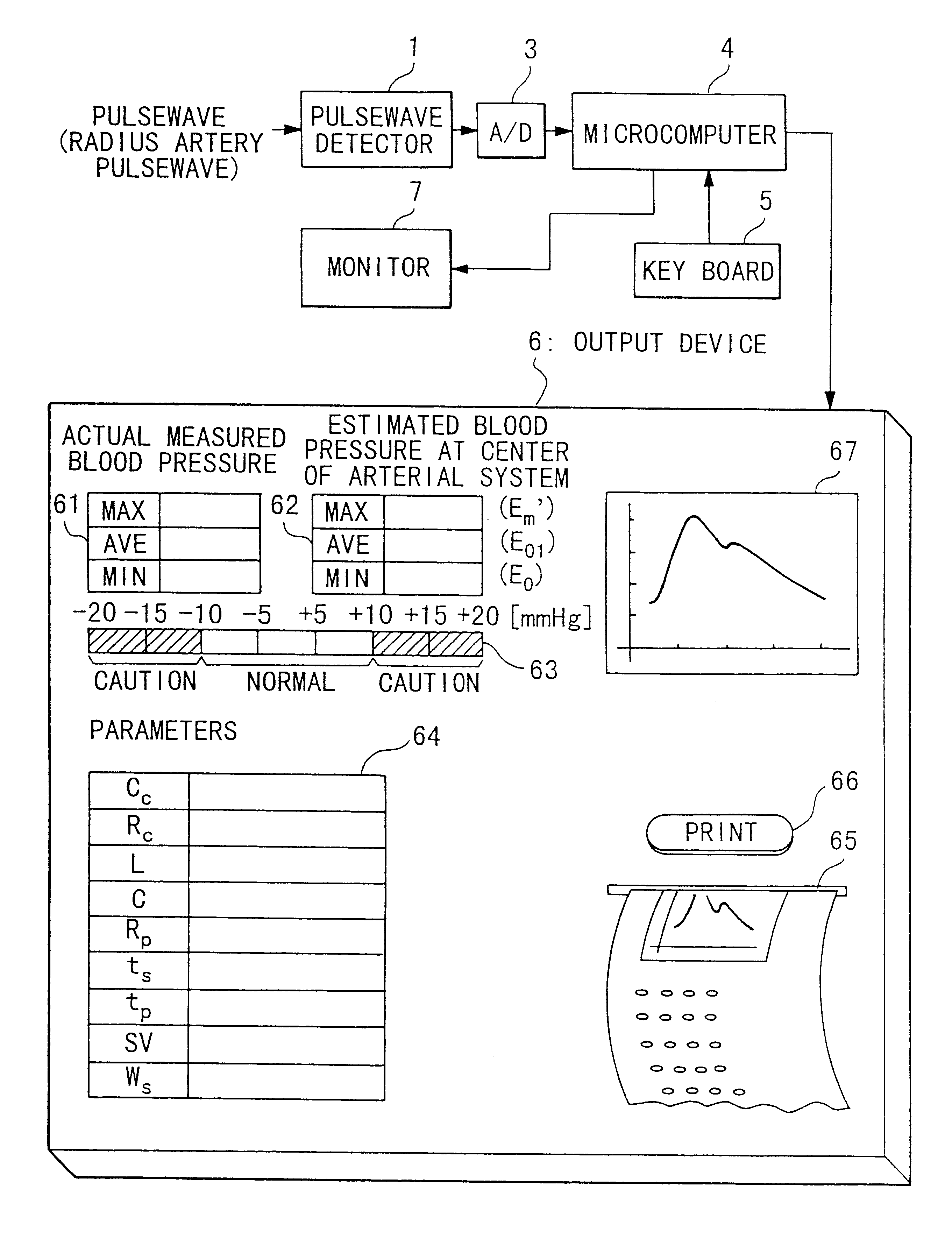
FIG. 1 is a block diagram showing the composition of the sphygmomanometer employed in this embodiment. In this embodiment, circulatory state parameters for the arterial system in the human body are evaluated based on information obtained from the body using non-invasive sensors. The specific details of these circulatory state parameters will be explained later.

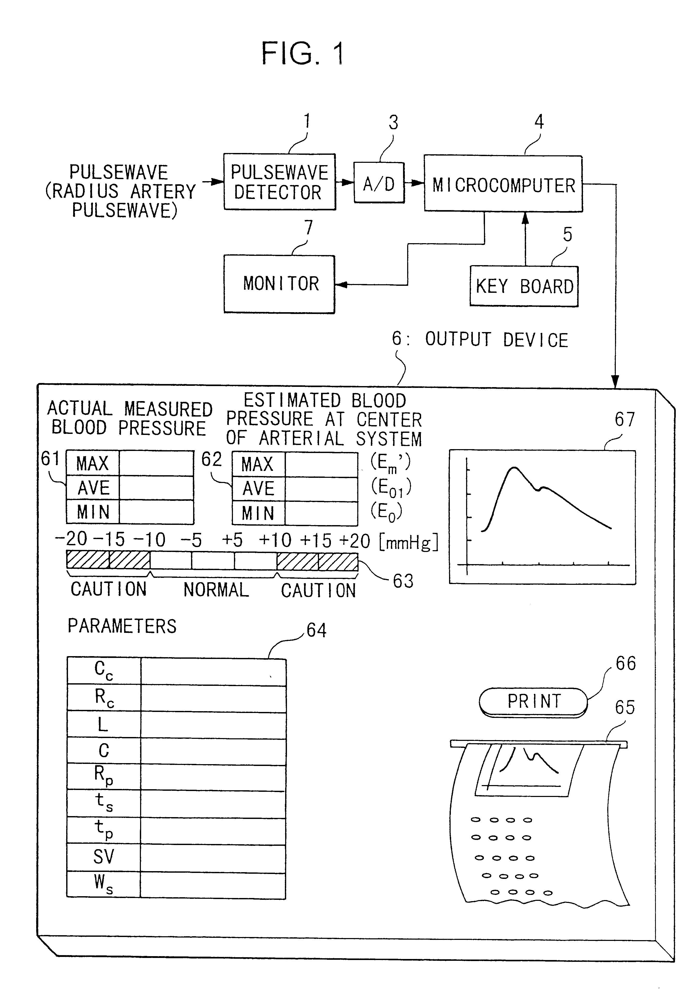
In FIG. 1, a pulsewave detector 1 detects the pulsewave at the radius artery via a pressure sensor S2 which is attached to the wrist of a test subject as shown in FIG. 2. Additionally, pulsewave detector 1 detects the blood pressure of the test subject via a cuff S1 attached to the upper arm of the subject as shown in FIG. 2. Pulsewave detector 1 corrects the measured radius artery pulsewave for blood pressure, and outputs the result as an analog electric signal. The analog signals are input to an A / D (analog / digital) converter 3, and are co...


PUM


Abstract

A non-invasive device for evaluating circulatory state parameters, and specifically, a pulsewave analysis device capable of evaluation by separating blood vessel compliance and blood vessel resistance into central and peripheral components of the arterial system is provided. Microcomputer 4 detects the waveform at a test subject's radius artery via pulsewave detector 1, and uptakes the stroke volume in the test subject which is measured by a stroke-volume measurer. Next, based on the measured stroke volume, microcomputer 4 adjusts the values of each element in a lumped five parameter model made up of an electrical circuit which models the arterial system from the center to the periphery of the body, so that the response waveform obtained when an electric signal corresponding to the pressure waveform at the proximal portion of the aorta in a test subject is provided to the electric circuit coincides with the waveform at the radius artery. Microcomputer 4 then outputs the thus-obtained values of each element as circulatory state parameters. In addition, microcomputer 4 calculates the diastolic pressure value, systolic pressure value and pulse waveform at the proximal portion of the aorta from the values of each element, and outputs the calculated result to output device 6.

Description

1. Field of the InventionThe present invention relates to an optimal device for measuring physiological state which is used to measure conditions in the human body. More specifically, the present invention relates to a device for analyzing pulse waves used to diagnose the circulatory system in the human body, and to a sphygmomanometer which evaluates compliance and resistance in the blood vessels at the center and periphery of the circulatory system based on the physiological state measured at the periphery of the human body, and estimates blood pressure at the center of the circulatory system.2. Background ArtBlood pressure and heart rate are most commonly used when diagnosing the condition of the circulatory system in the human body. However, in order to carry out a more detailed diagnosis, it becomes necessary to measure the so-called circulatory state parameters of compliance and viscous resistance in the blood vessels. Moreover, in the case where these parameters are expressed ...

Claims


Application Information

Patent Timeline
Patent Type & Authority Patents(United States)
IPC IPC(8): A61B5/026A61B5/021A61B5/029A61B5/02
CPCA61B5/02A61B5/021A61B5/029A61B5/681A61B5/02108
Inventor AMANO, KAZUHIKOUEBABA, KAZUOISHIYAMA, HITOSHI
Owner SEIKO EPSON CORP
Why Eureka
Try Eureka