
Incremental tuning process for electrical resonators based on mechanical motion

a technology of mechanical motion and electric resonators, applied in the field of electric resonators, can solve the problems of severe limitations in the size and cost of the components contained in the electronic components, and the method is not, however, without, to achieve the effect of improving the control of the deposition area

Inactive Publication Date: 2002-01-15
AVAGO TECH INT SALES PTE LTD
View PDF25 Cites 58 Cited by
  • Summary
  • Abstract
  • Description
  • Claims
  • Application Information

AI Technical Summary

Benefits of technology

Such a process alleviates the need to know the precise rate of etching in a particular process because etching will stop when the etching process removes all the material of one layer and reaches the next layer that is selected to be impervious to the etching process. In other words the etching stops each time at the barrier, i.e. the change from one material to another, as each layer is sequentially removed.

Problems solved by technology

Consumer electronics such as cellular telephones and miniature radios place severe limitations on both the size and cost of the components contained therein.
This method is not, however without problems as the presence of a mask needed to control the deposition over the desired electrodes creates problems of its own.
On the other hand if the mask is not in contact with the device the control of the deposition area suffers.
Such masking techniques have been successful with quartz type resonators that are much larger, but have not been as successful with resonators of the order of less than one millimeter.
With current technology, however, etching is not as controlled a process as deposition.
Etching tends to be less uniform, smooth or reproducible than deposition.
However, monitoring of the resonant frequency during etching is not possible when wet etching processes are used.

Method used


Image

  • Incremental tuning process for electrical resonators based on mechanical motion
  • Incremental tuning process for electrical resonators based on mechanical motion

Examples


Embodiment Construction

)

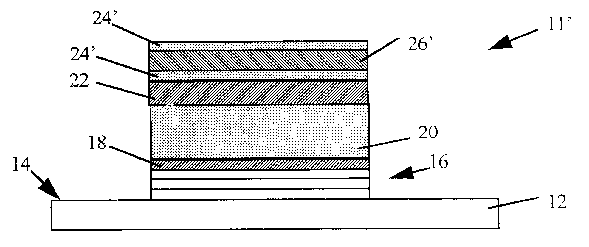
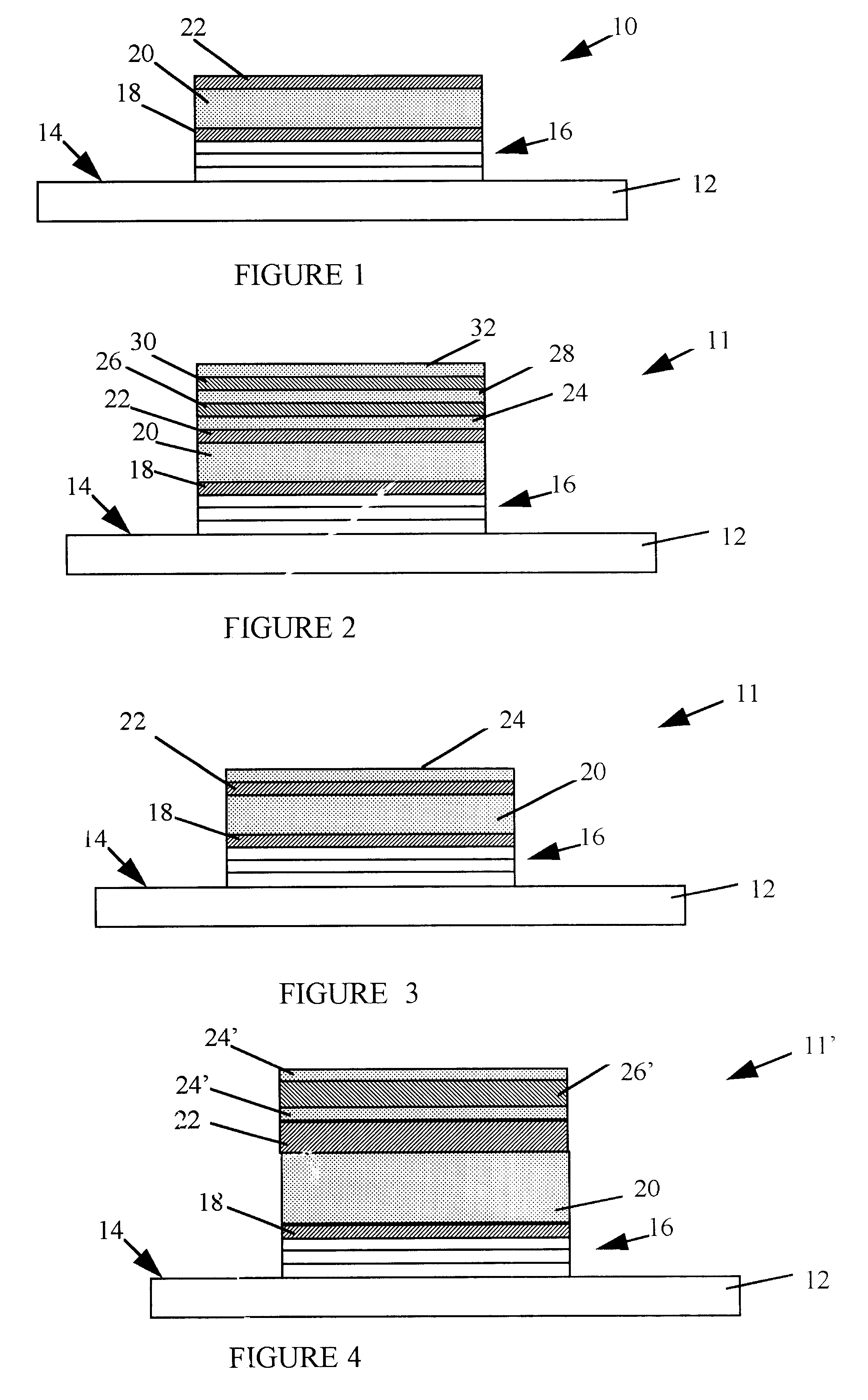
Throughout the following detailed description, similar reference characters refer to similar elements in all figures of the drawings. Depending on the thin film materials used, additional layers of insulation, protective films, encapsulation, etc. may be required and all such layers and films have been omitted herein for simplification and better understanding of the invention. The specific structure and fabrication method illustrated is for exemplary purposes only and other methods of fabricating a resonator and or filter in accordance with the present invention can be devised including but not limited to substrate etching, adjustment layers, reflecting impedance matching layers, etc. U.S. Pat. No. 5,373,268, issued Dec. 13, 1994, with the title "Thin Film Resonator Having Stacked Acoustic Reflecting Impedance Matching Layers and Method", discloses a method of fabricating thin film resonators on a substrate.

Referring now to FIG. 1, there is shown a typical structure of a mechanica...


PUM

PropertyMeasurementUnit
Thicknessaaaaaaaaaa
Frequencyaaaaaaaaaa

Abstract

The present invention is a method for adjusting the resonant frequency of a mechanical resonator whose frequency is dependent on the overall resonator thickness. Alternating selective etching is used to remove distinct adjustment layers from a top electrode. One of the electrodes is structured with a plurality of stacked adjustment layers, each of which has distinct etching properties from any adjacent adjustment layers. Also as part of the same invention is a resonator structure in which at least one electrode has a plurality of stacked layers of a material having different etching properties from any adjacent adjustment layers, and each layer has a thickness corresponding to a calculated frequency increment in the resonant frequency of the resonator.

Description

1. Field of the InventionThis invention relates to electrical resonators employing a mechanical transducer and more particularly to a method for fine tuning such resonators following batch fabrication.2. Description of Related ArtThe need to reduce the cost and size of electronic equipment has led to a continuing need for ever smaller filter elements. Consumer electronics such as cellular telephones and miniature radios place severe limitations on both the size and cost of the components contained therein. Many such devices utilize filters that must be tuned to precise frequencies. Hence, there has been a continuing effort to provide inexpensive, compact filter units.One class of filter element that meets these needs is constructed from mechanical resonators such as acoustic resonators. These devices use acoustic waves, bulk longitudinal waves for example, in thin film material, typically but not exclusively piezoelectric(PZ) material. In one simple configuration, a layer of PZ mate...

Claims


Application Information

Patent Timeline
IPC IPC(8): H03H3/04H03H3/00B44C1/22G04F5/06
CPCG04F5/063H03H3/04H03H9/131H03H9/175H04R31/00H04R17/10H03H2003/0428H04R15/02Y10S29/016Y10T29/435Y10T29/49004Y10T29/49005Y10T29/42
Inventor BARBER, BRADLEY PAULWONG, YIU-HUEN
Owner AVAGO TECH INT SALES PTE LTD
Learn More