All known sensors arranged in tires have the
disadvantage of requiring an electric supply
voltage.
However, most drivers only consider this feasible if the battery has a service life of more than three years.
a
low frequency of transmission signals per time unit (which appears feasible for monitoring the air pressure, but can only be utilized for traction control purposes by limiting the control precision),
Although devices of this type were successfully tested in experimental automobiles, they have not been incorporated into a
series production so far, wherein the incorporation into systems that also serve for traction control purposes, i.e., systems according to the present invention, currently appears improbable due to limitations of currently available batteries.
In addition, batteries of this type are difficult to exchange or can be easily stolen.
The elasticities, masses and oscillatory pulses between the sensors and the tire contact area (caused by stiffness fluctuations of rolling bearings and driving elements) diminish the precision of the measurement.
However, this effect also complicates the measurement of the longitudinal force which is of the utmost importance.
; the higher slip required by these other tires is, however, not even reached due to the cautious nature of the controller which is based on the steepest .mu.-slip curve stored in said controller.
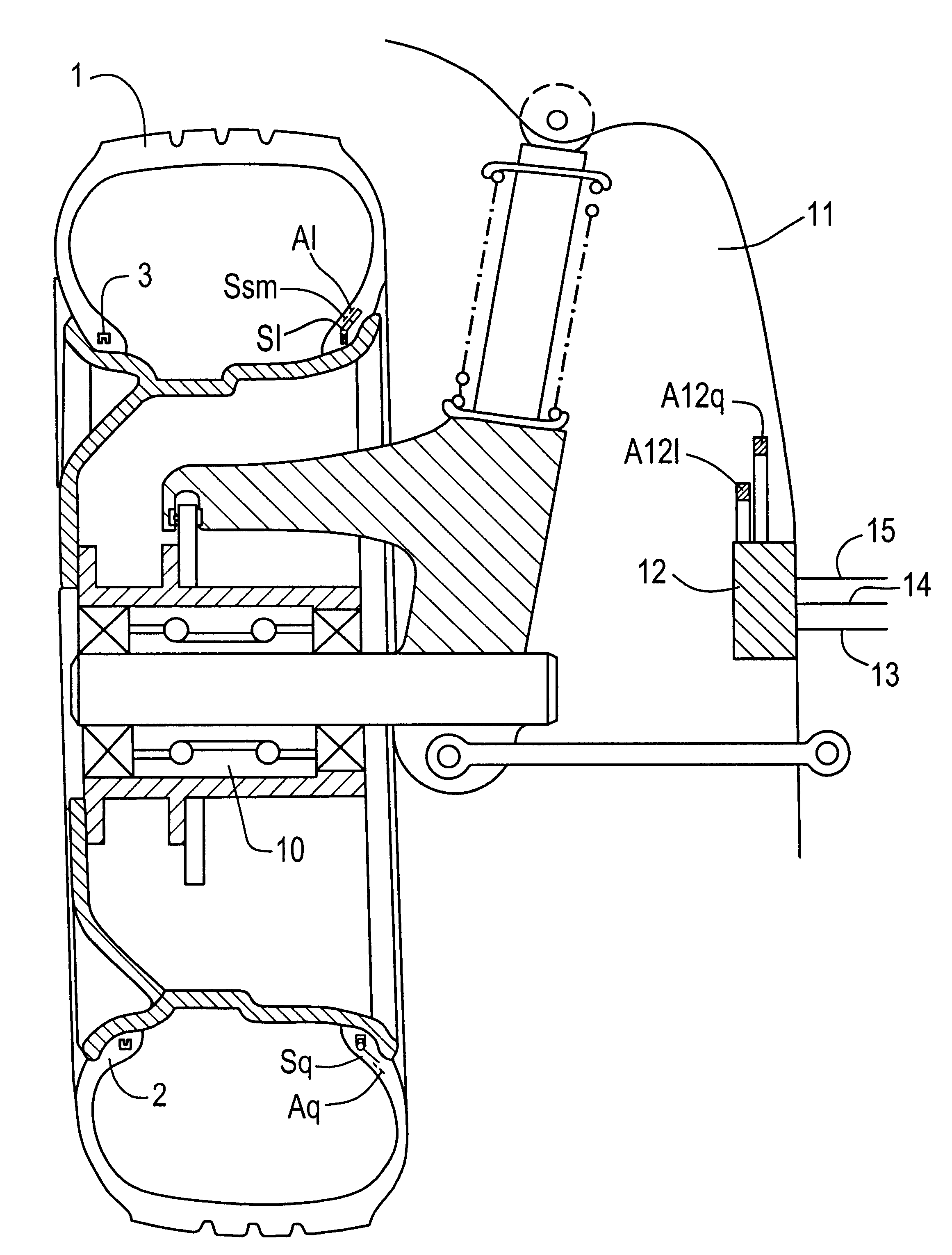
The sensor arrangement according to the invention within the bead region has the
disadvantage that the mechanical deformations to be sensed at this location are significantly smaller than, for example, the mechanical deformations occurring between the belt
edge region and the bead region in the
system according to PCT / EP95 / 03864.
This means that both constellations cause irregularities in the
stress field and the deformation field--although irregularities of different types.
The irregularities in the
stress field lead to lateral stress concentrations in the rubber layer surrounding the sensor.
The irregularities in the deformation field lead to eccentricities.
Consequently, it is not possible for the magnetic track to be removed by abrasion, e.g., when the tire contacts a curb stone.
In addition, a weight increase--which is unavoidable when embedding magnetizable particles--is prevented.
The sensor arrangement within the bead region also results in a particularly
low distortion of the calibration curves when standing
waves occur in the tire
tread and side wall region--which is typical in the high-speed range.
Due to the fact that the required
signal transmission path is maintained so short, the risk of receiving external signals is relatively low.
In the previously known concurring
system according to PCT / EP95 / 03864 by the same assignee, certain complications arise due to the fact that the mechanical
calibration curve, i.e., the longitudinal force transmitted by the tire as a function of the tire side wall torsion, depends on the air pressure.
Some customers consider this an unfair pricing policy by the manufacturer.
However, an increase in the air pressure also causes stretching (=reduction in bulge) of the strength carrier.
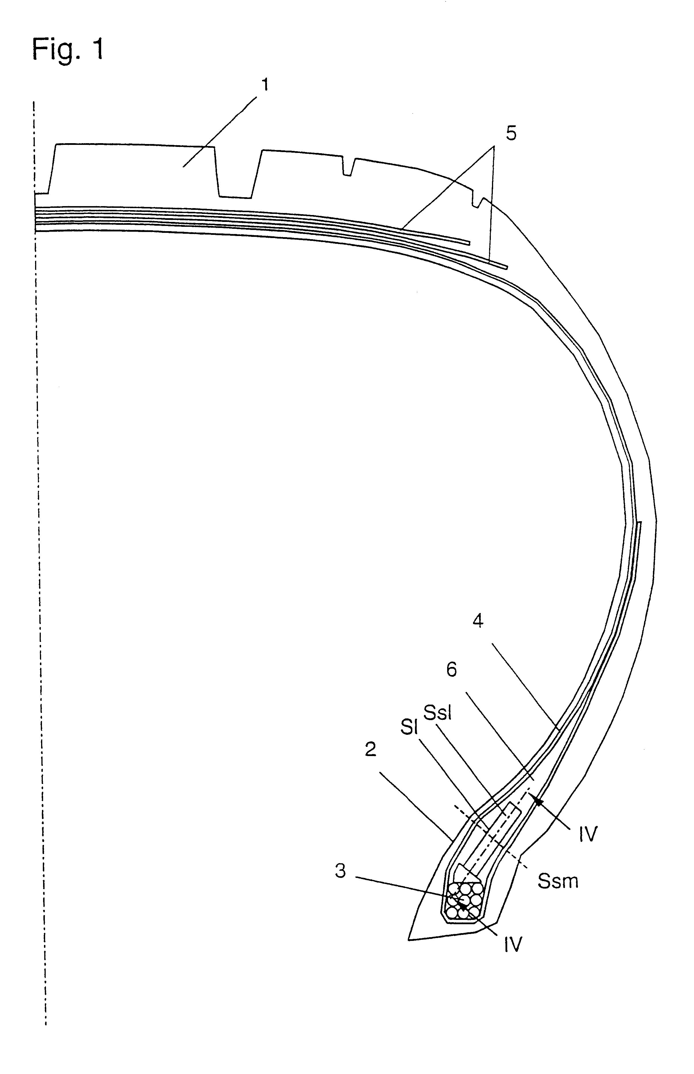
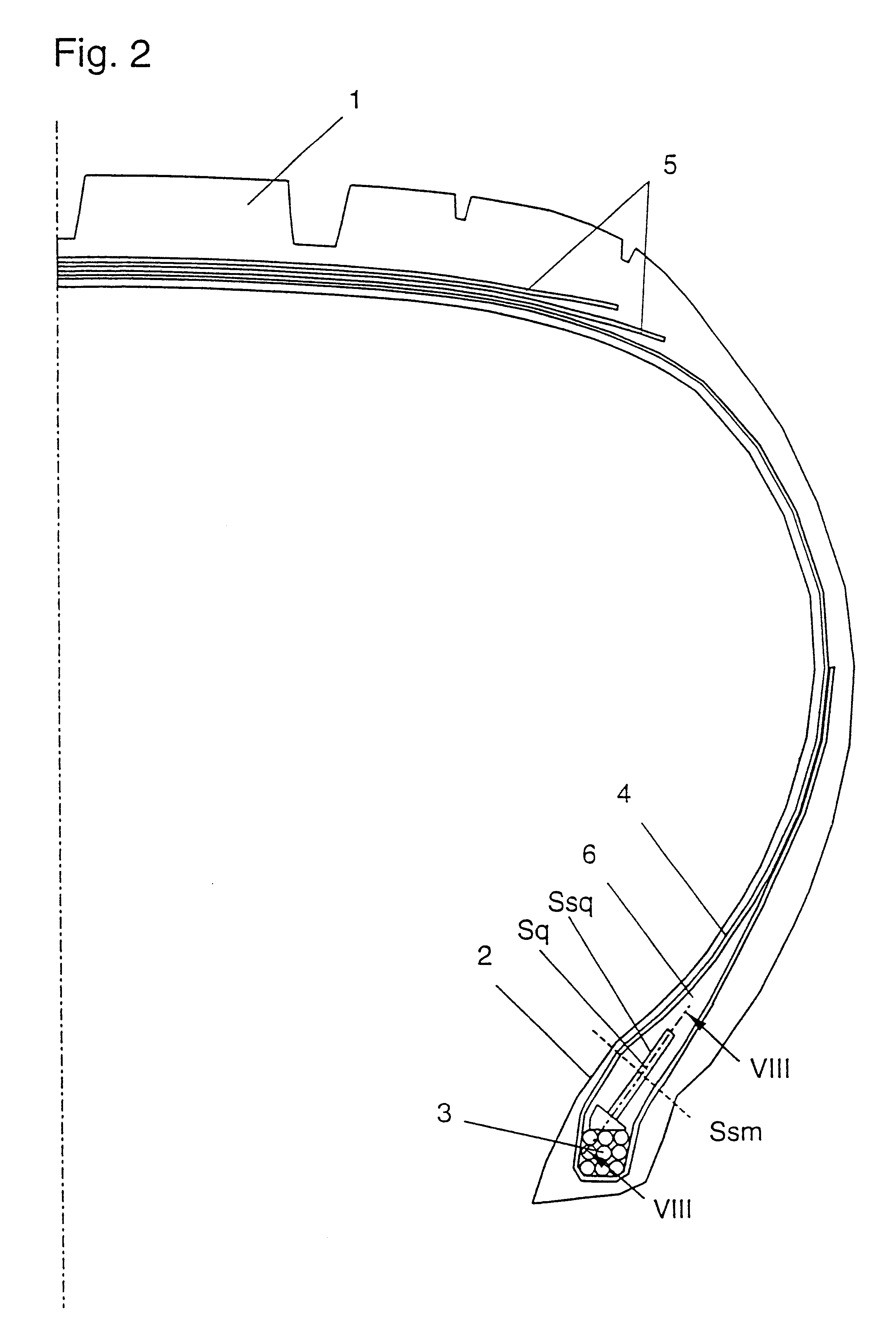
However, a reduction in bulge cannot occur at locations at which no bulge exists, i.e., in the point of inflection of the carcass.
However, a gradual displacement of the air pressure calibration scale must be expected over very long operating times due to air
diffusion in the
load cell.
Although it is possible to determine system variables on one and the same tire with sensors of different design, such compromise solutions result in more disadvantages than advantages.
However, practical experiments showed less favorable results.
The inventors believe that these inferior results are caused by the fact that the aforementioned equations are no longer entirely correct when a sensor passes through a phase region, in which the tire
tread is flattened in contrast to the initially assumed ideal circumstances.
This embodiment which is advantageous for the manufacture of prototypes is, however, not preferred for a
series production because a different tire would be required for each wheel position, i.e., it would be extremely difficult to obtain appropriate replacement tires.
In addition, a
synergistic combination characterized by the fact that the radial center (Ssm) of each sensitive surface (Ss) is arranged at the radial distance from the bead bore core (3) at which the cross section of the carcass (4) has a point of inflection results in the required cable lengths becoming very short or even zero.
However, an excessively high price for sensors, in particular, OFW sensors, contradicts the realization of such an embodiment.
However, the data obtained in positions which are not exactly situated vertically above or underneath or horizontally in front or behind the
rotational axis can only be evaluated after linking the data with suitable trigonometric functions.
In addition, the risk of a double reception--i.e., an erroneous identification--becomes higher the closer the various transmission and reception devices are arranged relative to one another.
However, the
data processing, in particular, the preferred automatic calibration of the friction
control system, would become more difficult due to the necessity of acquiring the respective rotational angle, wherein the
signal with the lowest chronological resolution also defines the chronological resolution of the entire
data set; however, the positions of the rotational angles can only be measured with an accuracy of approximately + / -30 in conventional systems (this corresponds to 60 markings on the circumference).
Due to this measure, this wave is prevented from attenuating to such a degree by the
hysteresis-caused attenuation on the surrounding rubber that the energy for the electromagnetic back-transmission is no longer available.

