
Knowledge driven composite design optimization process and system therefor

a composite design and optimization process technology, applied in the field of knowledge-driven composite design optimization process and corresponding system, can solve the problems of high component weight, inability to integrate well with local laminate definitions, and inability to understand the laminate design. , to facilitate the later update of the knowledge base, the effect of facilitating the understanding of the laminate design

Inactive Publication Date: 2002-01-22
MCDONNELL DOUGLAS
View PDF12 Cites 59 Cited by
  • Summary
  • Abstract
  • Description
  • Claims
  • Application Information

AI Technical Summary

Benefits of technology

Still another object of the knowledge driven composite design optimization process according to the present invention is to provide a composite design optimization process wherein manufacturing constraints for a part are considered as soon after the part geometry is defined as possible.
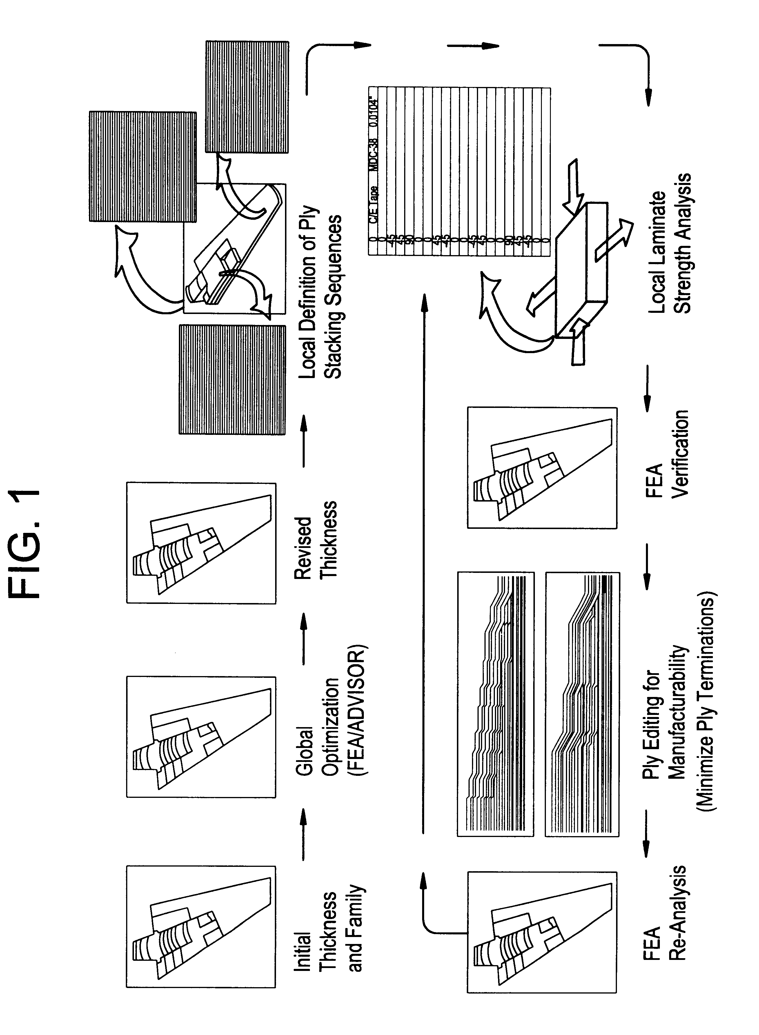
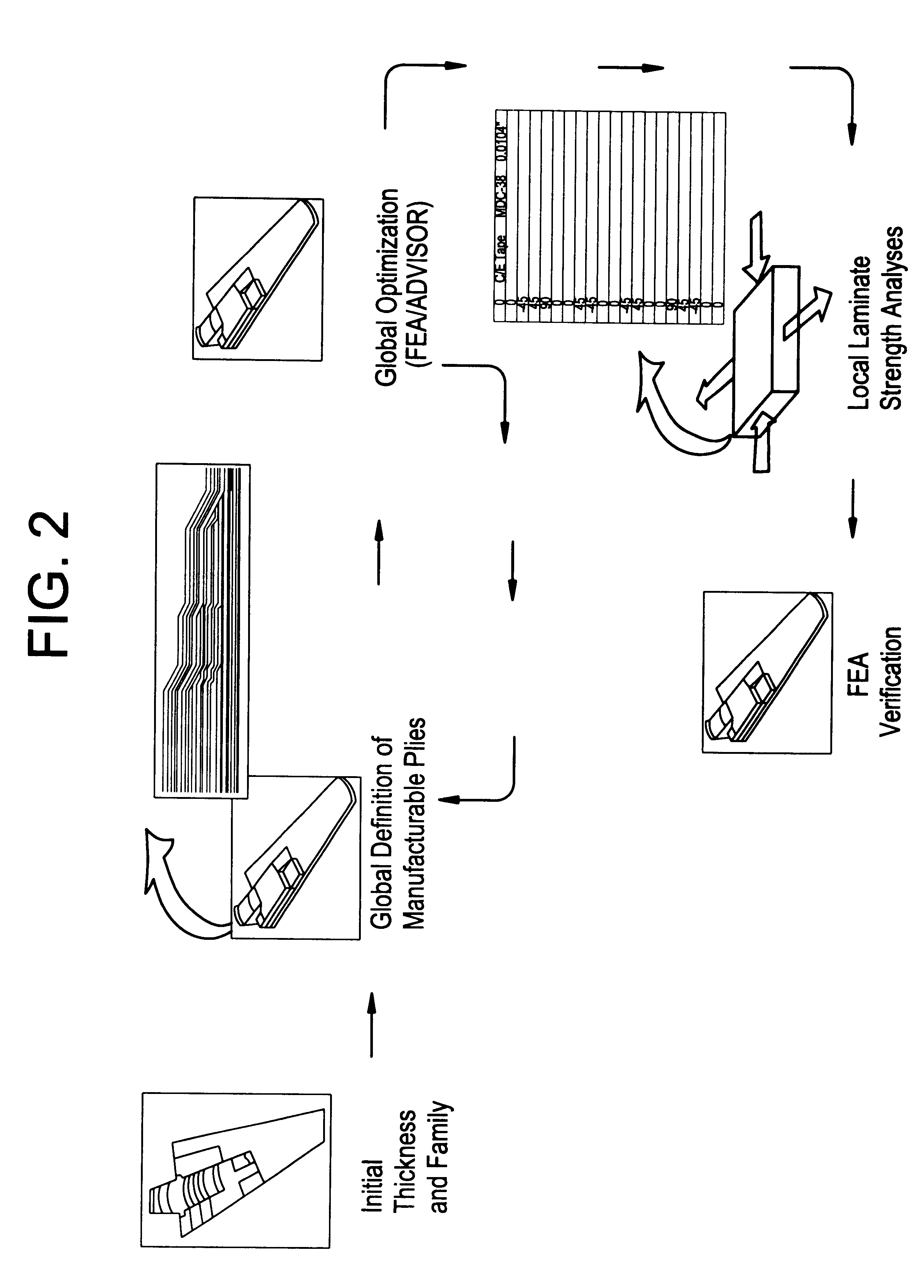
Another object of the knowledge driven composite design optimization process according to the present invention is to provide a composite design optimization process capable of presenting the intermediate stages of, and resultant, laminate design in several different formats to facilitate understanding of the laminate design at the ply level by all members of the laminate design team.
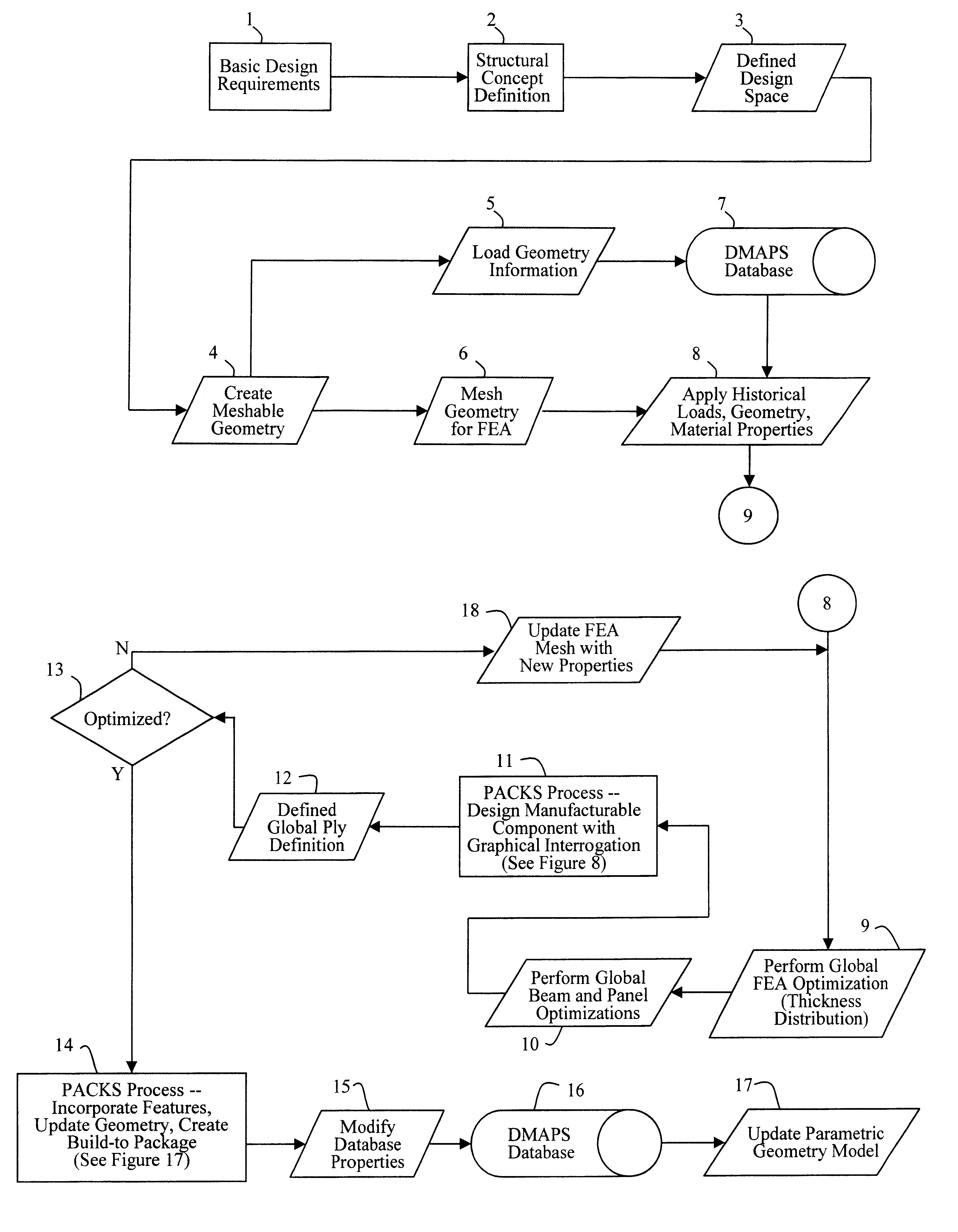
Advantageously, PACKS addresses these problems by creating one parametric model for composite design and analysis which outputs a three dimensional (3-D) definition of the composite laminate at the ply level. The PACKS module preferably integrates several new or existing tools into one shell, linking the outputs from, for example, the UNIGRAPHICS (.TM.) CAD program module, an analysis database, e.g., a PATRAN (.TM.) database, and the laminate designer subroutine while incorporating a number of rules of laminate design to increase the speed of the composite definition process. Beneficially, data developed by PACKS can be fed directly into manufacturing and analysis databases, or preferably is linked into a common database which feeds all processes.

Problems solved by technology

The use of composites in airframe construction is becoming an increasingly complex process.
However, since the abovementioned modifications occur after the bulk of the analysis has been completed, there are often surprises, e.g., higher than expected component weight, at a point well into the design process.
In addition, even when the analyst does define local stacking sequences, the analyst accomplishes this by performing optimizations which result in local laminate definitions which do not integrate well with one another.
When design changes occur, these errors and omissions are compounded because the text data is often only partially updated after each design change.
Translation errors due to selection of the incorrect normal orientation during this step are a common occurrence when working with complex geometry, primarily because standards do not address this level of detail.
The lack of geometrical accountability for ply overlaps leads to locally undersized areas in tools.
This in turn results in increased local pressure on the component during the cure at ply overlap or splice areas.
This may contribute to internal laminate defects in the form of porosity or resin poor areas in a structure if enough of these details occur through the thickness in an area.
In addition, lack of geometrical accountability can lead to local distortion of the fiber architecture and can result in increased interlaminar shear stress, each of which adversely affects structural performance.
These cause and effect relationships are viewed as too complex for the current conventional composite process to track and control during design and fabrication.
It will be appreciated from the references, discussed briefly below, that a great deal of attention is paid to these effects at the micromechanics level in literature and in the typical fabrication shop for specific structures, yet no standard process allows easy incorporation of these considerations into composite design practices.
It will be appreciated that this is an expensive and time-consuming approach to understanding a geometrical problem.
In addition, manufacturing constraints such as material width restrictions are not incorporated or reflected in the design data.
It will be noted that this results in additional ply splices which may not be accounted for in the design.
While this often leads to structural degradation, these manufacturing constraints may not be reviewed during the design steps in current practice.
The most common impacts of this approach are greater structural weight, more stringent fabrication requirements, and, of course, higher costs.
The lack of understanding of the structural design impacts on fabrication also leads to inconsistent disposition of discrepant fabrication events, since a "preferred" or "best" practice has never been identified.
Database coordination for design changes is a challenging, not to mention a continuous, process.
The CCDP program is limited in that it does not create a 3-D product definition, is hard coded in FORTRAN to run on a VAX computer or computer cluster, and includes no adaptive knowledge or objects that can assist the designer in tracking sensitivities of design changes.
Moreover, the CCDP program is not focused on visualization, parametric definition, or 3-D design capabilities.
While the CCDP program does a relatively good job of integrating manufacturing data needs into the program and outputting documentation, the CCDP program simply cannot provide any documentation in the form of blueprints or other visual aids.
In addition, the CCDP program is unable to duplicate the optimum laminate selection of an analyst without manual intervention.

Method used


Image

  • Knowledge driven composite design optimization process and system therefor
  • Knowledge driven composite design optimization process and system therefor
  • Knowledge driven composite design optimization process and system therefor

Examples


Embodiment Construction

The knowledge driven composite design optimization process according to the present invention was developed as a response to the inefficiencies noted in the conventional composite design process, which was described in detail above. These inefficiencies were discovered during the process flow evaluation. The process according to the present invention overcomes these deficiencies by building a single data structure for the composites definition that expands the current Design, Manufacturing and Producibility Simulation (DMAPS) goals for parametric design of composites and then refines the parametrics within the composite laminate definition to the ply level. This is the first key facet of the present invention, since plies are the lowest entities the manufacturing shop handles. Many of the errors that occur during the manufacturing process are due to the lack of understanding of ply location in three-dimensinonal dimensional (3-D) space and how these plies change (propagate or termin...


PUM


Abstract

A knowledge driven composite design optimization process for designing a laminate part includes steps for generating a globally optimized 3-D ply definition for a laminate part, and modifying the 3-D ply definition to include features of the laminate part, where the generating and modifying steps are parametrically linked to one another and are performed in the recited order. Preferably, the generating step includes substeps for determining connectivity between a plurality of regions defining the laminate part, subsequently generating ramp features detailing interconnection of the regions defining the laminate part, and displaying views and corresponding tabular data describing the laminate part and illustrating both inter-region connectivity and the ramp features as specified by a user. A knowledge driven composite design optimization system and associated computer memory for operating a general purpose computer as a knowledge driven composite design optimization system are also described.

Description

BACKGROUND OF THE INVENTIONThe present invention relates generally to a composite materials design process. More specifically, the present invention relates to a knowledge driven composite design optimization process and corresponding system. A computer program adapted to facilitate implementation of the knowledge driven composite design optimization process is also disclosed.The use of composites in airframe construction is becoming an increasingly complex process. Composite structures are generally designed at the local laminate level using wireframes or solids in Computer Aided Design (CAD) systems such as the UNIGRAPHICS (.TM.) CAD system. Analysis is performed using a separate analytical model(s), e.g., a finite element based model, which initially assumes laminate families which define a percentage composition (number) of each ply orientation and which is generally coordinated with design geometry through imported master datums and a design surface. A typical design process is...

Claims


Application Information

Patent Timeline
IPC IPC(8): G06F17/50
CPCG06F17/50G06F30/00G06F2113/26G06F30/15G06F2113/24G06F2111/04
Inventor VASEY-GLANDON, VIRGINIA M.HALE, RICHARD D.SCHMITZ, JEFFREY J.
Owner MCDONNELL DOUGLAS
Learn More