
Graphical user interface for testability operation

a testability operation and user interface technology, applied in the field of automatic testability operation, can solve the problems of increasing the complexity of the device employing the transistors, the difficulty of designing the interfaces, and the inability to accurately analyze the results. achieve the effect of more accurate analysis

Inactive Publication Date: 2002-01-22
ADVANCED MICRO DEVICES INC
View PDF7 Cites 43 Cited by
  • Summary
  • Abstract
  • Description
  • Claims
  • Application Information

AI Technical Summary

Benefits of technology

for all violations. When the atpg analysis error message level is active, rule checks require test generation to be turned on for more accurate analysis. When the atpgc error message type is active, the DFT tools use ATPG constraints to analyze appropriate rule checks. In addition, the Clock boxes 553 and 554 contain text entry boxes labeled "Clock Name" that enable the design engineer to specify a particular clock to use for analyzing design rule violations. FIG. 8 only displays a portion of the ATPG Setup window 550. The DFT tools check for many other design rule violations, allowing the design engineer to control the severity and message type levels of the tool.
Turning now to FIG. 9, illustrated is the "Synthesis Options" menu or window 560 which includes an Asynchronous Inputs box 561, a General Options box 562, an Extra Parameters box 563, a Compile Options box 564, an Optimization box 565 and a DFT Options box 566. The Asynchronous Inputs box 561 enables the selection of asynchronous inputs such as a master reset signal. In this example, the selected master reset signal is a RST_MAIN_L signal. The General Options box 562, by clicking with the mouse 25 on a button to the left of a "Compile requires DesignWare license" label, enables the selection of whether a requested compile usage of the EDA tool 235 requires a specific software license. In addition, the General Options box 562 enables the specification of shared block names by clicking with the mouse 25 on a button labeled "+" to the right of a "Shared block names" label.
The disclosed methodology and apparatus thus sets up scan and test logic for insertion using an EDA tool. This allows a design engineer to quickly, efficiently and accurately increase testability while still in the design phase of the development process. A system according to the present invention reduces the need to write complicated scan and test scripts by providing a GUI that enables the selection and de-selection of multiple options related to the design process in a one-pass flow. In addition, the settings of the GUI are design block specific, thus providing high configurability. The methodology implemented in the disclosed GUI also provides a substantial productivity improvement in the testability insertion and analysis of a design. A source code appendix is enclosed herein containing exemplary code, written in the Tc1 command language, capable of generating the disclosed GUI. Further, the design techniques according to the present invention can be applied to a variety of VLSI circuits.

Problems solved by technology

With astonishing regularity over the past several decades, transistors have become smaller and the devices that employ them have become more complex.
The job of designing these ICs has also grown correspondingly more difficult.
In addition, GUIs for ATPG were non-intuitive and did not interface with the synthesis flow.

Method used


Image

  • Graphical user interface for testability operation
  • Graphical user interface for testability operation
  • Graphical user interface for testability operation

Examples


Embodiment Construction

This application is related to the following co-pending, concurrently filed, and commonly assigned U.S. patent application which is hereby incorporated by reference:

U.S. patent application, entitled "Insertion of Scan Hardware" to Luis A. Basto and Mark T. Fox.

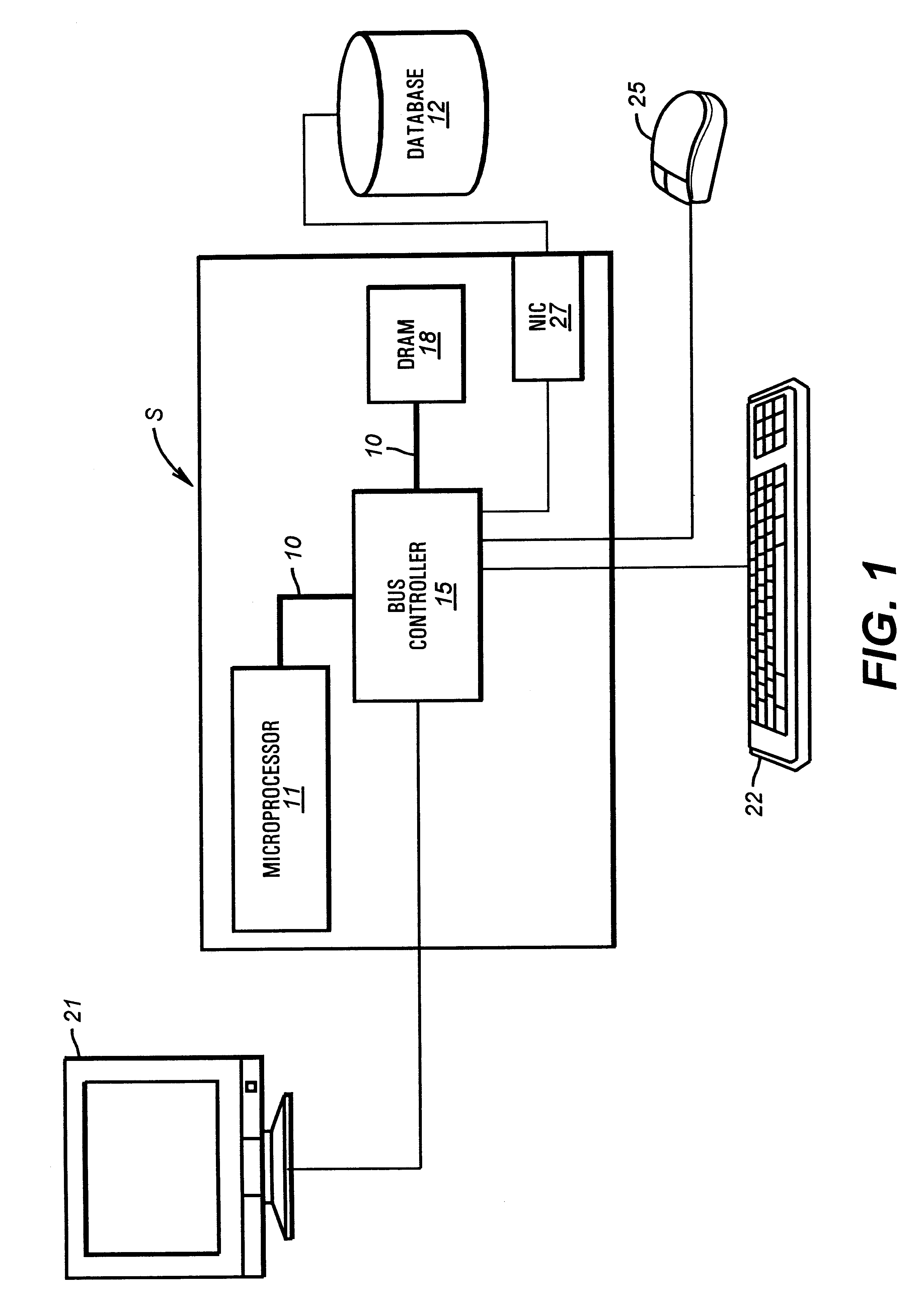
Turning to FIG. 1, illustrated is a computer system S upon which a graphical user interface (GUI) can be run. The computer system S may be configured around an internal bus 10 connected to a microprocessor 11 and a bus controller 15. Also included within the illustrated computer system S and connected to the bus 10 is a dynamic random access memory (DRAM) or other form of system memory 18. A video display 21, a keyboard 22, a network interface card (NIC) 27 and a mouse or other pointing device 25 are connected to the computer system S through circuitry in the bus controller 15, enabling human interaction with the computer system S. Finally, the NIC 27 is shown coupled through a network to a database 12.

The computer system S is...


PUM


Abstract

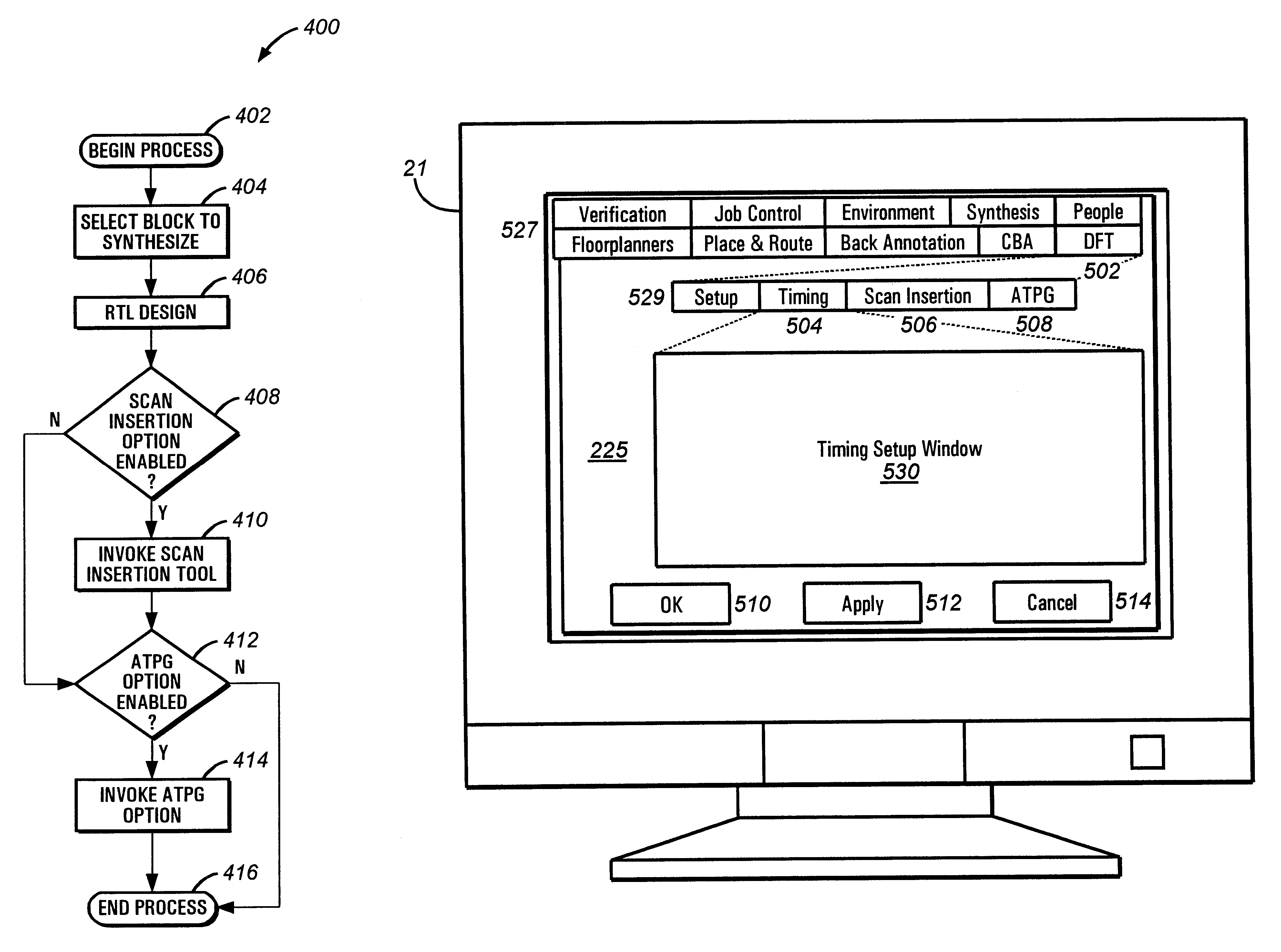
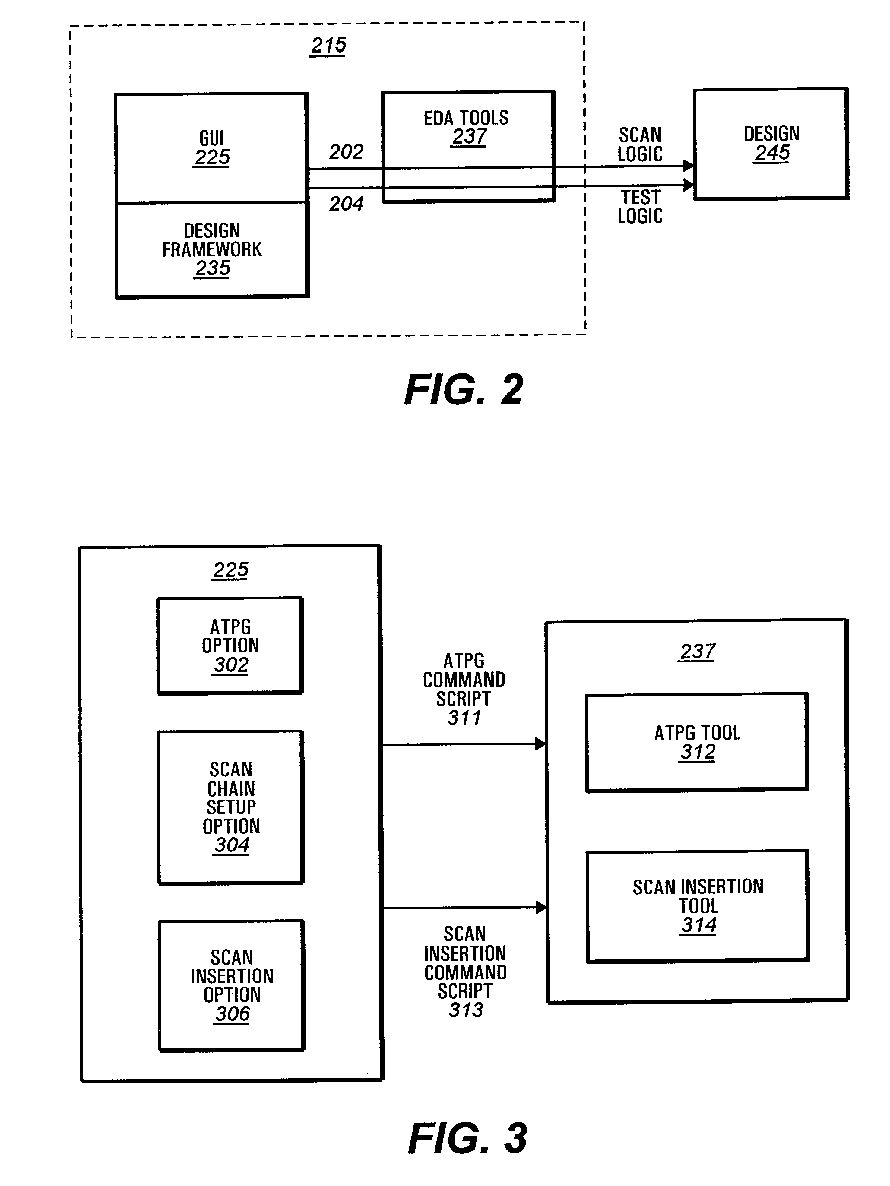
A graphical user interface (GUI) provides a design engineer the capability of automatically inserting scan logic and test logic into a design. The graphical user interface includes a scan insertion option for a design engineer to invoke a scan insertion tool to check the design for testability. The graphical user interface also permits the design engineer to invoke a test generation tool such as an automatic test pattern generator (ATPG) tool to check the design for fault coverage. The graphical user interface, which can serve as a front end for a design framework, enables a design engineer to efficiently increase testability while still in a design phase.

Description

1. Field of the InventionThe present invention generally relates to automating testability operation in connection with electronic design automation (EDA) software, and more particularly, to a graphical user interface (GUI) for testability operation.2. Description of the Related ArtWith astonishing regularity over the past several decades, transistors have become smaller and the devices that employ them have become more complex. Today it is not uncommon for an integrated circuit (IC) to contain millions of transistors. The job of designing these ICs has also grown correspondingly more difficult. What was once accomplished by a single individual or a small group of individuals is typically performed by a large team or multiple teams of design engineers.Although very large scale integration (VLSI) circuits have become more difficult to design, a number of tools have been developed to make the job easier. One class of tools that is makes the job more manageable is called electronic des...

Claims


Application Information

Patent Timeline
Patent Type & Authority Patents(United States)
IPC IPC(8): G01R31/3183G01R31/28G06F11/26
CPCG06F11/261G01R31/318342
Inventor BASTO, LUIS A.DOUGHERTY, W. DAVID
Owner ADVANCED MICRO DEVICES INC
Learn More