Method of making a signal transmission fuse

a signal transmission and fuse technology, applied in the field of signal transmission fuse making, can solve the problems of insufficient field use toughness, unacceptably high water vapor and oil permeability, and easy degradation of ionomers

Inactive Publication Date: 2002-02-19
DYNO NOBEL INC
View PDF23 Cites 24 Cited by
  • Summary
  • Abstract
  • Description
  • Claims
  • Application Information

AI Technical Summary

Benefits of technology

Generally, in accordance with the present invention, there is provided a signal transmission fuse in which a support tape has a reactive material containing a binder coated onto the tape. The reactive material, which may comprise known explosive / fuel mixtures or deflagrating compositions, or a mixture thereof, may be applied to the tape in the form of a reactive paint comprising the pulverulent reactive material, a binder and, optionally, a solvent. The coated tape is then encased within a tube, which may be a plastic (synthetic organic polymeric) tube, which is extruded or otherwise applied over the tape, so that the support tape separates the coating of reactive material from the, for example, hot, freshly extruded, plastic tube. The reactive material is thereby protected from contact with the hot, freshly applied outer tube and this gives more flexibility in selecting both the reactive material and the plastic because the degradation temperatures (defined below) of the components of the reactive material, such as an organic explosive, and the temperature at which the plastic tube is applied, are no longer constraining factors. The utilization of a binder retains the reactive material on the tape during manufacture and, in the finished product, prevents migration of the reactive material through the signal transmission fuse and enables the use of greatly increased core loadings of the reactive material. The increased core loadings may be made high enough so that, when an explosive / fuel mixture is employed as the reactive material, the signal transmission fuse is desirably ruptured upon use.

Problems solved by technology

One of the problems which Kristensen et al seeks to redress is the art-recognized problem of migration of the reactive material powder from the inner surface of the tube to form a loose powder in the tube.
While ionomers such as SURLYN plastics provide good adhesion of such reactive material, such ionomers are susceptible to degradation by ultraviolet radiation, have unacceptably high water vapor and oil permeabilities, and are insufficiently tough for field use.
However, the extrusion temperature of SURLYN plastics is too high to permit use of less expensive explosives such as PETN, which has a melting point of only about 141.degree. C., or even RDX, the 204.degree. C. melting point of which is less than about 20.degree. C. higher than the lowest SURLYN plastic extrusion temperature.
The thermally less sensitive explosives, such as HMX, are not only more expensive, but are less sensitive than explosives such as PETN and RDX, therefore reducing the reliability of initiation of the signal transmission fuse.
It has been found that extremely fine particles of such reactive material are difficult to uniformly and reliably apply by gravity flow.
This problem is overcome by using a somewhat larger particle size of the reactive material, but the larger particle size results in aggravating the problem of migration of the powder from the tube surface because the larger particles, being heavier, adhere less well to the tube inner surface.
The use of a larger particle size of the reactive material also tends to reduce the sensitivity of the reactive material to initiation, thereby requiring depositing somewhat heavier loadings of the reactive material powder which, in turn, further aggravates the powder migration problem.
Powder migration is a problem because, in products where lengths of the signal transmission fuse are connected to devices such as detonators, migrating powder can collect atop the explosive or pyrotechnic contained within the detonator and shield the explosive or pyrotechnic from the signal generated in the shock tube, thereby resulting in a misfire.
Further, deployment of a shock tube in the field results in bends and kinks in the shock tube, and a collection of migrated powder can block the shock tube at such bends or kinks, thereby interrupting transmission of the signal and also resulting in misfire.
Of course, if powder migration is so severe as to leave sections of the fuse with insufficient powder adhered thereto to sustain the reaction, a misfire will occur.
The term "degradation temperature", e.g., as applied to a material such as a reactive material, reactive coating, reactive paint or components thereof, means that temperature at or above which desired properties of the material will be adversely affected, e.g., the material or a component thereof may melt or otherwise be adversely affected.

Method used


Image

  • Method of making a signal transmission fuse
  • Method of making a signal transmission fuse
  • Method of making a signal transmission fuse

Examples


example 1

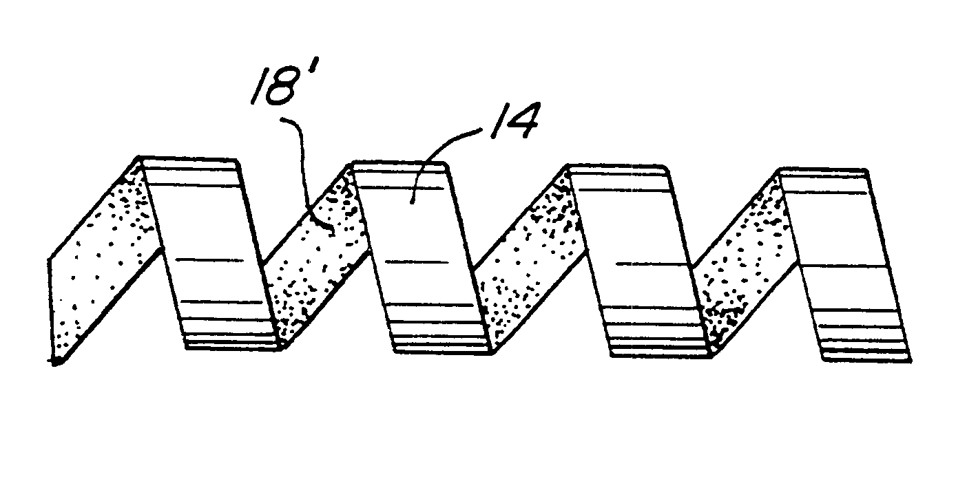
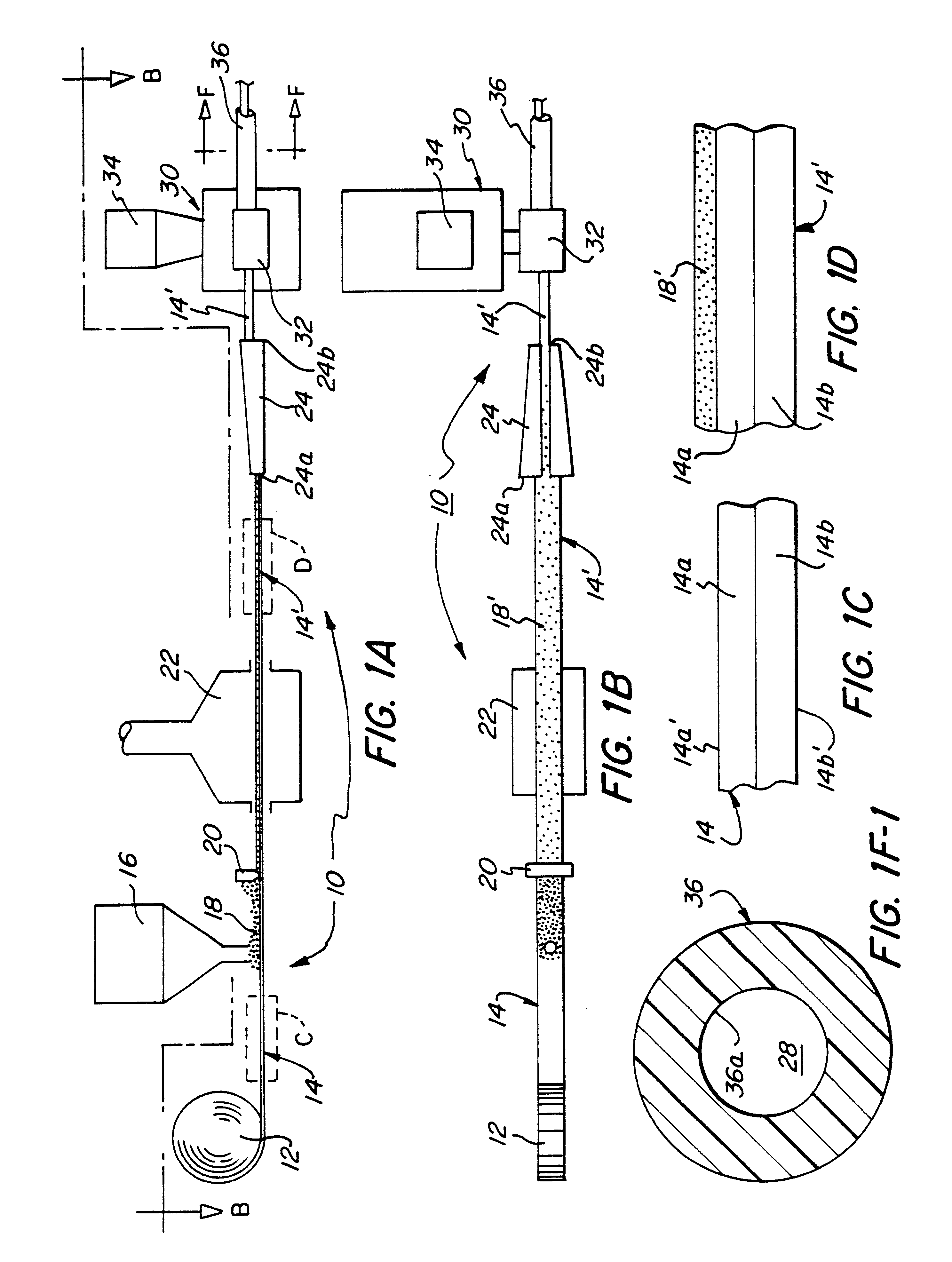
Explosive compositions comprising the reactive paints listed in TABLE I were applied to a two-layer support tape of polyethylene terephthalate and polyethylene, 5 mm in width, at a core loading of 20 to 40 g / m.sup.2, approximately equivalent to a linear core loading of 100 to 200 mg / m. The support tape was approximately 0.1 mm in thickness, the polyethylene terephthalate layer being 0.05 mm thick and the polyethylene layer being 0.05 mm thick. One of the reactive paints was applied to the polyethylene terephthalate side of a sample tape and dried to provide a dried coating.

The coated support tape is formed into a tubular or folded configuration with the polyethylene side on the exterior of the tubular or folded configuration and bonded to the inner surface of a tubular polyethylene sheath extruded about the folded, coated support tape. The extruded polyethylene tube had an inside diameter of 1.8 mm and an outside diameter of 4.0 mm. The folded, coated tape enclosed within the polyet...

example 2

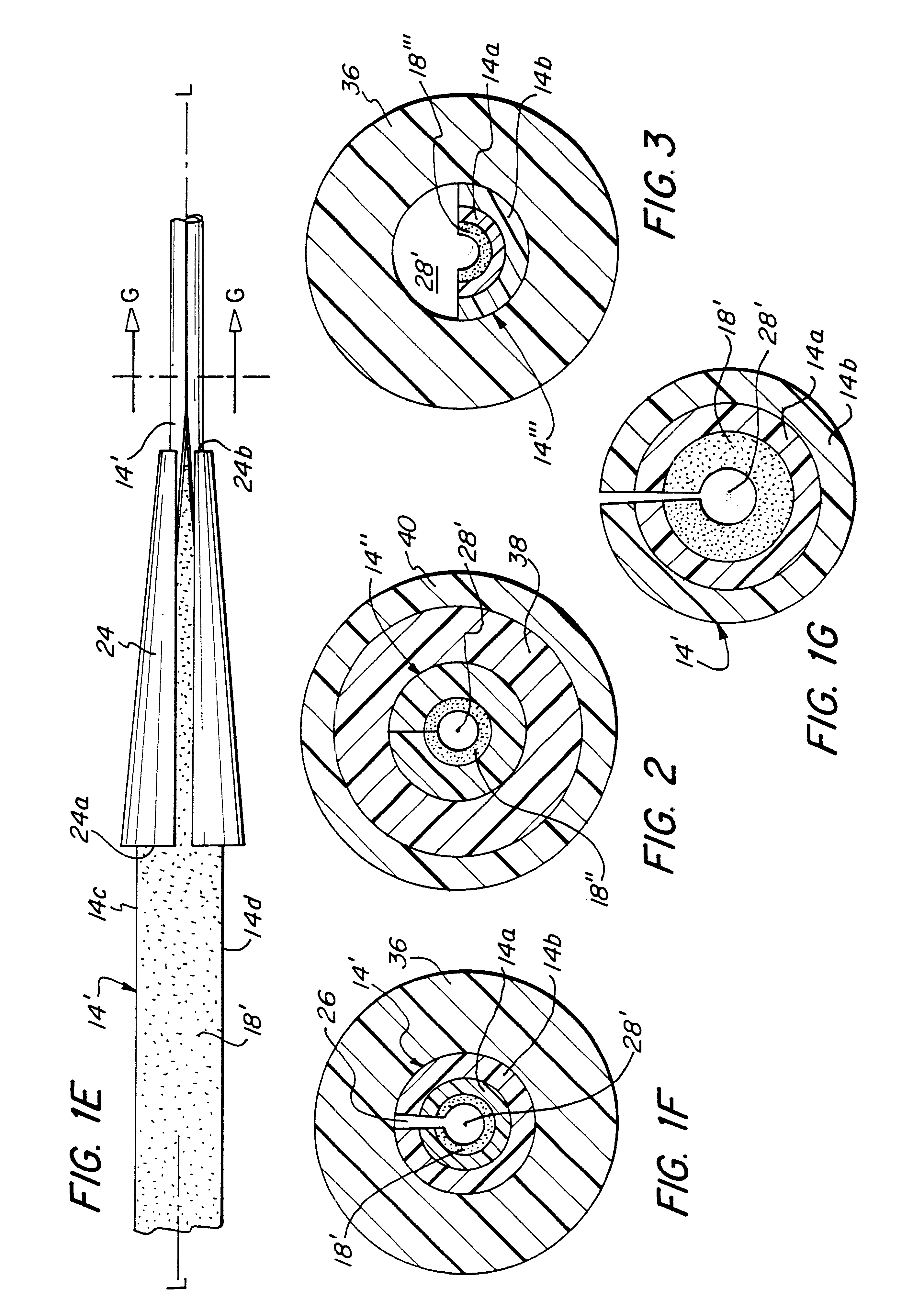
An explosive composition of each of the reactive paint compositions 1-4 of TABLE II, having various core loadings in the range of 40 to 200 g / m.sup.2, was applied to the polyethylene terephthalate side of a two-layer film of polyethylene terephthalate and polyethylene, 6 mm in width and 0.1 mm thick, the polyethylene terephthalate layer being 0.05 mm thick and the polyethylene layer being 0.05 mm thick. The coated tape is formed into a tape support with the polyethylene side on the exterior, and is bonded to the inside surface of a tubular polyethylene sheath as the tube is extruded about the tape support.

The polyethylene tube had an inside diameter of 2.0 mm and an outside diameter of 3.8 mm. An open space of about 0.28 mm diameter remained between the reactive coating on the support tape and the inner surface of the polyethylene tube. The open space extended along the length of the tube so that the dried coating was exposed to air along the length thereof.

A 10 meter length of each...


PUM

PropertyMeasurementUnit
temperatureaaaaaaaaaa
melting pointaaaaaaaaaa

Abstract

A signal transmission fuse is made of a tube (36) which encases a support tape (14) having a reactive coating (18') which is adhered to one side of the tape by a binder. A method of making the signal transmission fuse includes depositing on the support tape (14) a reactive paint (18) including a binder, which paint dries to form a reactive coating (18'). The coated support tape (14') is then folded, i.e., formed into a channel configuration, to provide an inner concave side of the tape on which the reactive coating (18') has been disposed. The coated support tape is then enclosed, e.g., within an extruded plastic tube (36). One side of the support tape may be made of a first material (14a) to which the reactive coating adheres, and a second side may be made of a second material (14b) which bonds or adheres to the inner surface (36a) of the plastic tube (36) enclosing the coated support tape (14'). The binder causes even high loadings of the reactive coating (18') to adhere to the coated support tape (14') to prevent reactive material migration. The support tape also shields the reactive material from the hot, freshly extruded surrounding plastic tube (36) during manufacture.

Description

The present invention relates to an improved signal transmission fuse, such as shock tube, of the type used for transmitting a detonation signal and, more particularly, to an improved tape-containing structure of such fuse, and to a method of making the same.RELATED ARTSignal transmission fuses of the type commonly referred to as shock tube are well-known in the art. U.S. Pat. No. 3,590,739, issued Jul. 6, 1971 to Per-Anders Persson, discloses a hollow elongated plastic tube having a pulverulent reactive substance, which may be constituted by a highly brisant explosive such as PETN, RDX, TNT or HMX, adhered by various means to the interior wall of the shock tube.U.S. Pat. No. 4,328,753, issued May 11, 1982 to L. Kristensen et al, discloses a low energy fuse in the form of a plastic tube comprised of concentric tubular plies of material on the inner surface of which is disposed a pulverulent reactive material. One of the problems which Kristensen et al seeks to redress is the art-rec...

Claims


Application Information

Patent Timeline
Patent Type & Authority Patents(United States)
IPC IPC(8): C06C5/00C06C5/08C06C5/04F42B3/10
CPCC06C5/00C06C5/08C06C5/04
Inventor RABOTINSKY, NICKOLAY ILIYCHFURNE, VLADIMIR VASILIEVITCHPECHENEV, URIY GENNADIEVITCHNIKITIN, IGOR VASILIEVITCHBELJANKINA, IRINA GENADIEVNAGLADDEN, ERNEST L.
Owner DYNO NOBEL INC
Why Eureka
Try Eureka