
Actuator system for aerospace controls and functions

a technology of aerospace control and actuator system, applied in the direction of automatic actuation, position/direction control, aircraft transmission means, etc., can solve the problems of relative oscillatory movement between, use of control tabs, and potential shock wave problems at aircraft velocities approaching sonic conditions,

Inactive Publication Date: 2002-02-26
BAE SYSTEMS PLC
View PDF14 Cites 30 Cited by
  • Summary
  • Abstract
  • Description
  • Claims
  • Application Information

AI Technical Summary

Benefits of technology

Its is also an aim of the present invention to provide an actuator system employing an electrical actuator which is compact and reliable and in which cooling requirements and power consumption are reduced.
means for aerodynamically assisting the electrical actuator in order to reduce the load on the electrical actuator in use.
The present invention combines the advantages of a relatively low powered electrical actuator with aerodynamic amplification of, or an aerodynamic reduction in resistance to, the force required for operating the aircraft control surface or other apparatus. Potentially, this can enable very significant reductions in actuator mass and size, and in the cooling requirements and power consumption.
Linear electric motor technology offers simplicity, low wear, low maintenance and high accuracy. In particular, linear electric motors are capable of long strokes, fast response times, and a high degree of positional accuracy compared with existing aircraft actuators. Although the achievable output forces compared with known actuation techniques are relatively low, this is compensated by the use of aerodynamic amplification or other aerodynamic assistance, for example in the form of control tabs.

Problems solved by technology

There were, however, a number of drawbacks to the use of control tabs, the most significant being potential risks of control surface flutter at resonant frequencies and potential shock wave problems at aircraft velocities approaching sonic conditions.
Flutter arises from a structural interaction between the aircraft frame and the control surface resulting in a relative oscillatory movement between them, which becomes exacerbated as resonant frequencies are approached.
However, hydraulic systems are prone to leakage and wear, and ensuring that they remain at all times in a satisfactory operating condition requires a high level of maintenance.
A number of proposals have been put forward and are employed in limited applications, but hitherto no satisfactory electrically powered actuation system has yet been produced.
This system suffers from all of the disadvantages of the known hydraulic actuator systems, together with the additional problems that the power source has a high mass, is expensive to produce and requires a substantial amount of aircraft space.
Such arrangements suffer from problems of wear and a tendency to jam, which is a significant drawback considering the safety requirements in aircraft flight.
A further difficulty in employing electrical actuation systems for aircraft control surfaces concerns the dissipation of heat, particularly for high load, high duty cycle devices, especially in the kinds of environment in which many actuators are required to function.
However, as indicated above, this leads to a new set of problems.
Significantly increased actuator cooling problems
Increased actuator cost.
Another problem concerns the power requirements for the currently proposed and available electrical actuators.
This poses a significant safety risk in passenger applications.

Method used


Image

  • Actuator system for aerospace controls and functions
  • Actuator system for aerospace controls and functions
  • Actuator system for aerospace controls and functions

Examples


Embodiment Construction

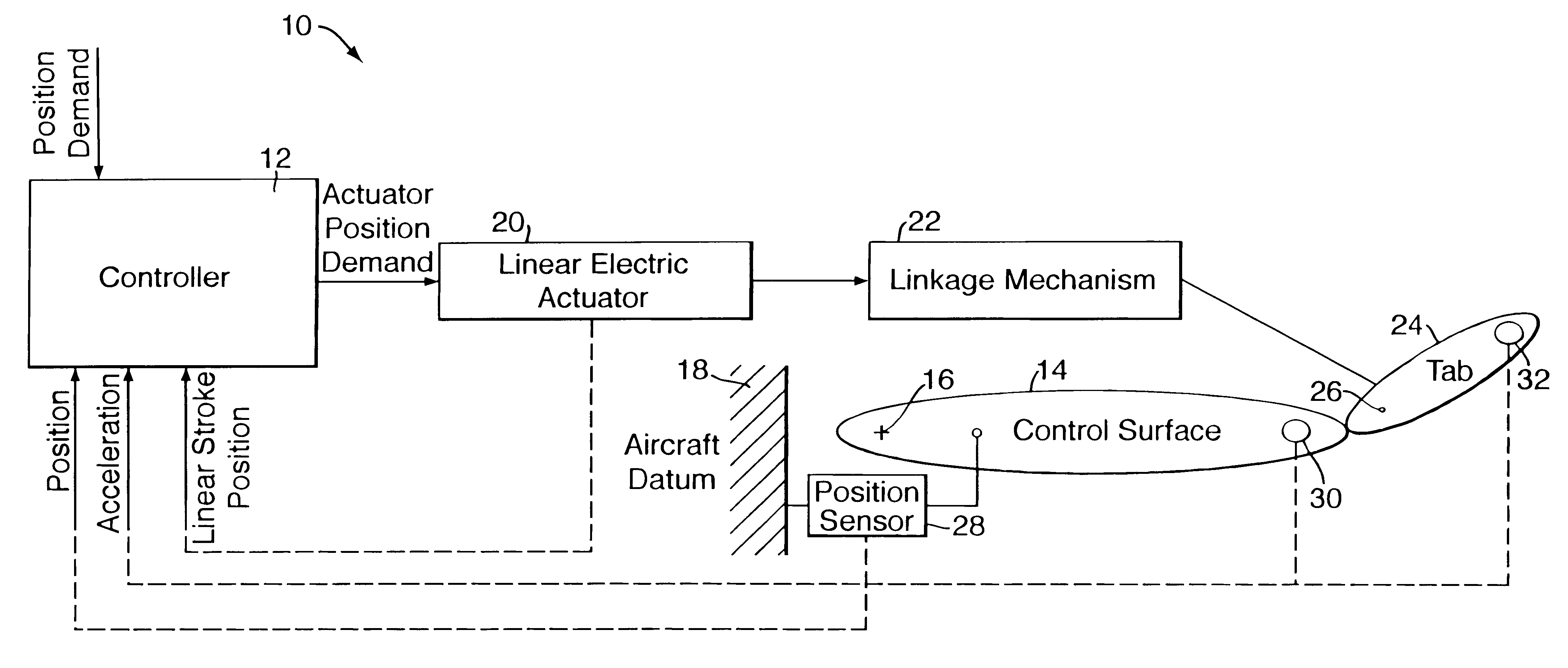
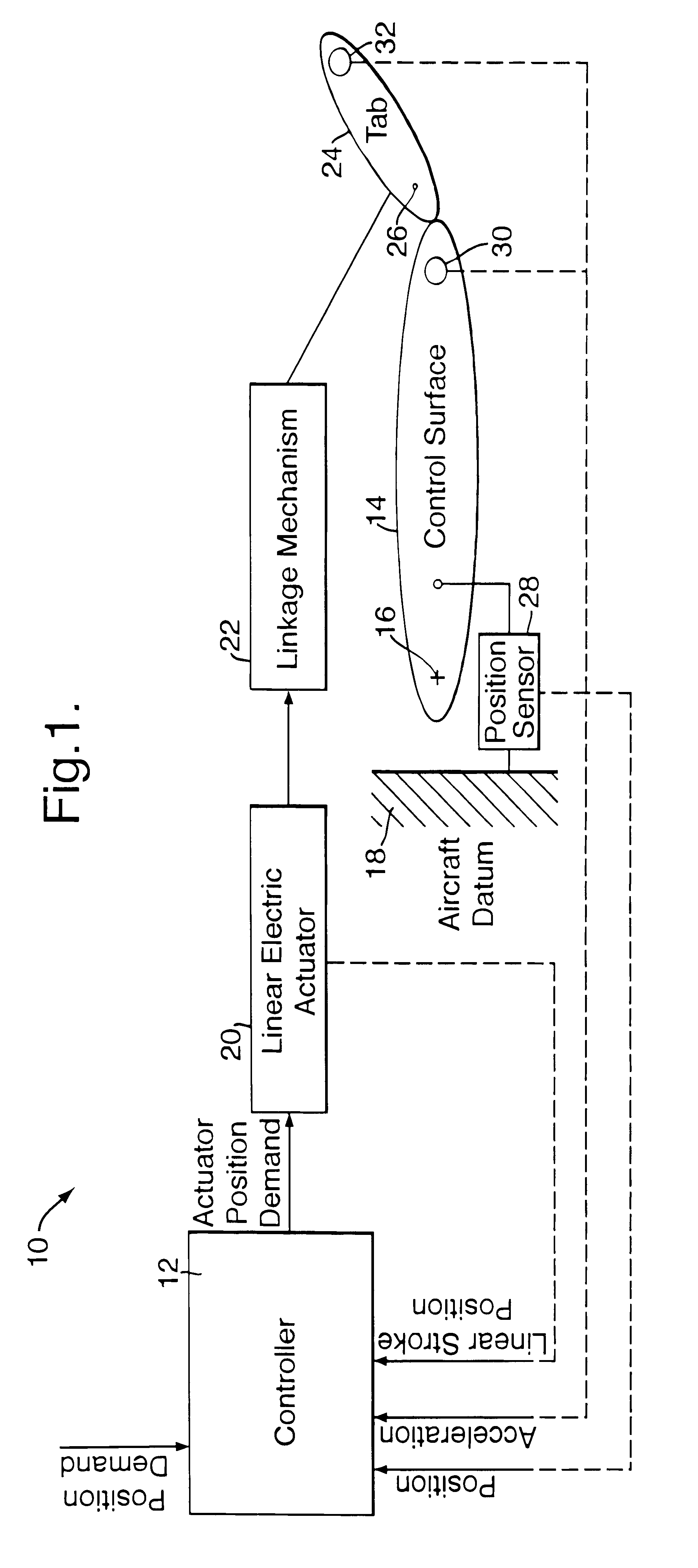
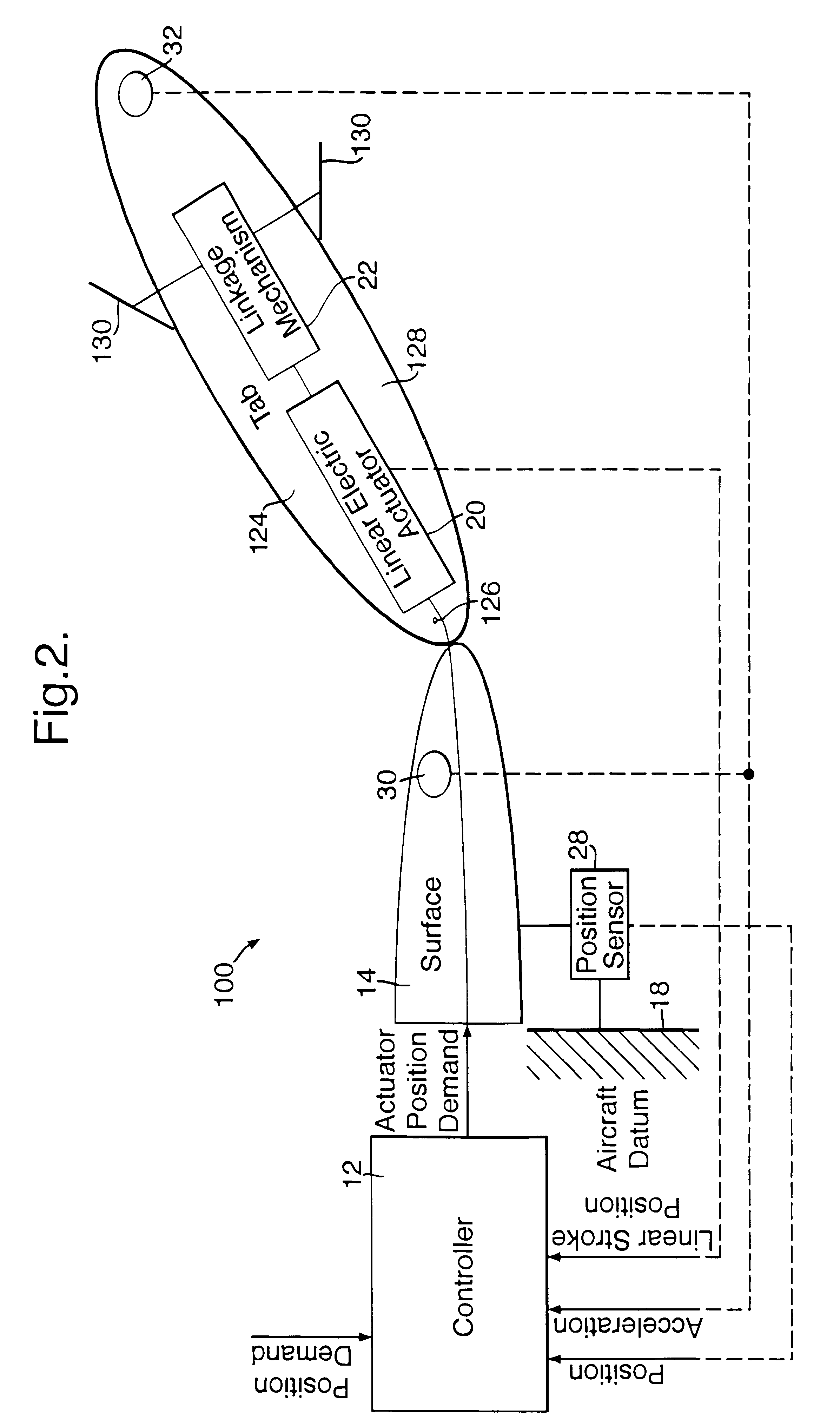
Referring initially to FIG. 1, this shows an actuator system 10 according to the present invention for operating an aircraft control surface, such as the ailerons, the wing leading edge and trailing edge flaps and slats, or flaperons, the elevators, the spoilers or the rudder. In the present instance, the control surface is an aileron or flaperon.

As shown, the actuator system 10 comprises a controller 12, which may be a part of the flight control computer or which may be a part of another aircraft system. The controller 10 is located within the frame of the aircraft for operating a control surface 14 attached by a main pivot 16 to a wing 18 of the aircraft. The pivot 16 is appropriately placed relative to the control surface 14 to provide a balanced mounting for the surface 14.

The controller 12 is connected to an electric actuator 20 in the form of a linear electric motor, wherein the shaft and armature comprise a moving slide or carriage running on an air gap above a flat stator. T...


PUM


Abstract

An actuator system (10, 100, 200) for use in an aircraft control or operating system, comprising a controller (12) operable in response to an input for generating a control signal, and an electrical actuator (20) responsive to the control signal for operating an aircraft flight control surface or other aircraft apparatus. A tab (24; 124) for aerodynamically assisting the electrical actuator is also provided in order to reduce the load on the electrical actuator in use.

Description

1. Field of the InventionThe present invention concerns actuator systems for aerospace controls and other aerospace functions. In particular, the invention concerns an actuator system for operating the aerodynamic control surfaces of an aircraft such as the ailerons, the wing leading edge and trailing edge flaps and slats, i.e. the flaperons, the elevators, the spoilers and the rudder. The actuator system of the present invention may also be employed for controlling the airbrakes, arrester hook, flight re-fuelling probe, the undercarriage or pallets, and the doors and locks generally.2. Discussion of Prior ArtActuator systems for operating aircraft control surfaces and for performing other aerospace functions are well known. Early such systems were in the form of mechanical linkage and lever arrangements operated manually by means of a control column or rudder bar by which the pilot could directly adjust the deflection of the aerodynamic control surfaces, for example.Then, as aircra...

Claims


Application Information

Patent Timeline
IPC IPC(8): B64C9/10B64C13/00B64C13/50B64C9/00
CPCB64C13/50B64C9/10
Inventor UTTLEY, ANDREW E.CHAMBERS, PETER WILLIAMBLACKWELL, NIGELWELLER, BRIAN
Owner BAE SYSTEMS PLC
Learn More