Direct digital synthesis pixel clock generator

a digital synthesis and generator technology, applied in the field of electrotrophotographic marking, can solve the problems of high cost, difficult to obtain such scan lines from multiple imaging assemblies, and scan lines that, unless corrected, are shorter or longer than ideal

Inactive Publication Date: 2002-02-26
XEROX CORP
View PDF4 Cites 15 Cited by
  • Summary
  • Abstract
  • Description
  • Claims
  • Application Information

AI Technical Summary

Problems solved by technology

However, they are relatively expensive since multiple charging, exposing, and developing stations are required.
However, obtaining such scan lines from multiple imaging assemblies is very difficult.
For example, manufacturing tolerances in producing and assembling exposure stations result in scan lines that, unless corrected, are shorter or longer than ideal.
1. Changes in scan velocity during the scan. Given a uniform rotational velocity of the raster polygon, the ends of the scan line are scanned at a faster rate then at the center of the scan line (assuming that the polygon is centered on the photoreceptor). This is known as scan line non-linearity. It has the effect of displacing image information along the scan line from its desired location. While the F-theta post-scan optical system 26 reduces scan line non-linearity, in a typical system non-linearity errors of +2 pixels are common.
2. Facet to facet jitter. Each facet of the polygon may have slight imperfections that cause the laser beam to have shorter or longer flight times compared to the other facets. In a typical system, with the scan lines synchronized by the Start-of-Scan signal, the ends of the scan lines receive the full effect of the facet to facet imperfections. In a typical imaging assembly errors of +1 / 2 pixels are common.
3. Misalignment of an imaging assembly with the photoreceptor. This causes the scan line length to vary and also produces scan line nonlinearities. While scan line nonlinearities can be improved by changing the average frequency of the pixel clock, known as Magnification Correction, there remains a residual error known as Keystoning that can add +1 pixels of non-linearity to the scan.
Without correction the foregoing errors result in color mis-registration and color distortion.
Scan lines that are longer or shorter than ideal are akin to fast scan direction magnification errors.
While variable frequency phase-locked pixel clocks can successfully correct relatively large errors, they have less success correcting for small errors or for making fine scan line length adjustments.
This is partially because correcting small errors requires difficult-to-achieve small pixel clock frequency adjustments.
Unfortunately, correcting small errors in the scan line is important for high quality color imaging.

Method used


Image

  • Direct digital synthesis pixel clock generator
  • Direct digital synthesis pixel clock generator
  • Direct digital synthesis pixel clock generator

Examples


Embodiment Construction

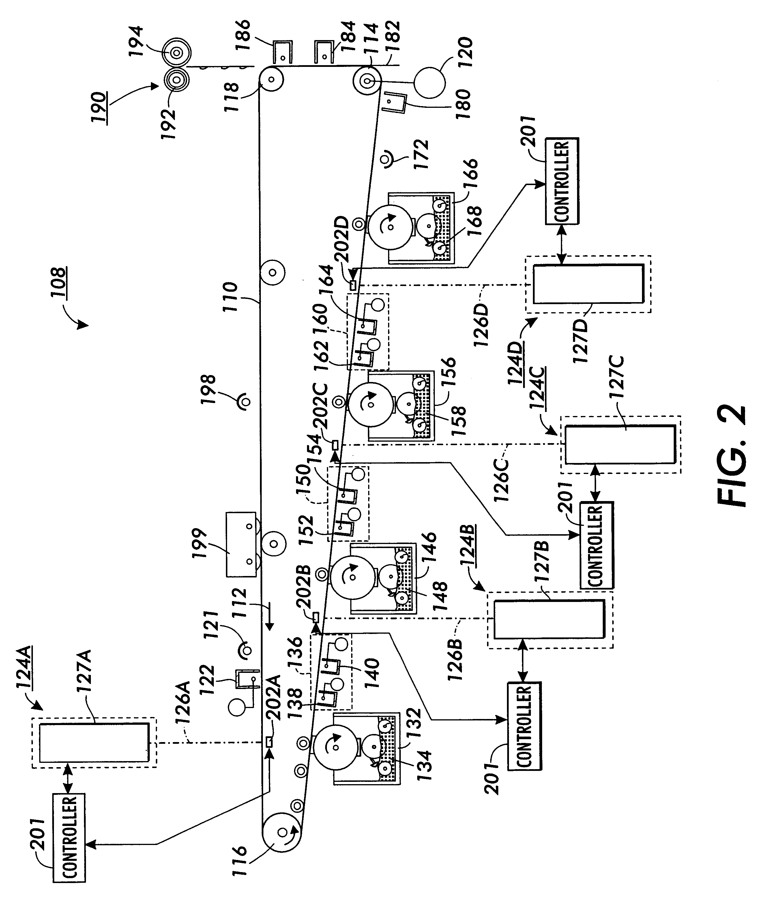
FIG. 2 illustrates a single pass, Recharge-Expose-and-Develop, Image-on-Image (Read IOI) color printer 108 that is in accord with the principles of the present invention. However, it is to be understood that the present invention is applicable to many other machines. Therefore, it is to be understood that the following description of the color printer 108 is only to assist the understanding of the principles of the present invention.

The color printer 108 includes a photoreceptor belt 110 which travels in the direction indicated by the arrow 112. Belt travel is brought about by mounting the photoreceptor belt about a driven roller 114 and about tension rollers 116 and 118, and then driving the driven roller 114 with a motor 120.

As the photoreceptor belt travels each part of it passes through each of the subsequently described process stations. For convenience, a single section of the photoreceptor belt, referred to as the image area, is identified. The image area is that part of the ...


PUM


Abstract

A Direct Digital Synthesis pixel clock generator for use in electrophotographic printers. A controller receives a start-of-scan signal and a facet 0 signal. In response, the controller sends a pre-stored frequency control word to a Direct Digital Synthesis Oscillator. The Direct Digital Synthesis Oscillator sends pulses at a frequency that depends on the frequency control word to a Digital Phase Shift Circuit. The controller also applies a sequence of delay profile words to the Digital Phase Shift Circuit. Each delay profile word causes the Digital Phase Shift Circuit to delay a contemporaneous pulse from the Direct Digital Synthesis Oscillator between 0° and 360° degrees, with the actual delay depending upon the delay profile word. The delay profile words are selected such that scan line pixels are "adjusted" in position. A phase-locked-loop circuit integrates and smoothes the frequency step changes. The output of the phase-locked loop circuit is applied to a synchronizer that synchronizes the pixel clocks with the start-of-scan. Alternatively, the controller applies a sequence of frequency profile words to a Direct Digital Synthesis Oscillator. The Direct Digital Synthesis Oscillator then generates pulses at a rate that depends upon the applied frequency profile word. The frequency profile words are selected such that the pixels are "adjusted" in position. A phase-locked-loop circuit then integrates and smoothes the output of the Direct Digital Synthesis Oscillator. The resulting pulse frequency is applied to a synchronizing circuit that synchronizes the pixel clocks with the start-of scan-signals.

Description

This invention relates to variable frequency oscillators used in imaging assemblies of electrophotographic printing machines.BACKGROUND OF THE PRESENT INVENTIONElectrophotographic marking is a well-known, commonly used method of copying or printing documents. Electrophotographic marking is performed by exposing a charged photoreceptor with a light image representation of a desired document. The photoreceptor is discharged in response to that light image, creating an electrostatic latent image of the desired document on the photoreceptor's surface. Toner particles are then deposited onto that latent image, forming a toner image, which is then transferred onto a substrate, such as a sheet of paper. The transferred toner image is then fused to the substrate, usually using heat and / or pressure, thereby creating a permanent record of the original representation. The surface of the photoreceptor is then cleaned of residual developing material and recharged in preparation for the productio...

Claims


Application Information

Patent Timeline
Patent Type & Authority Patents(United States)
IPC IPC(8): G02B26/12G06K15/12G02B26/10B41J2/44G03G15/04G03G15/043H04N1/113
CPCG06K15/1219G02B26/127
Inventor SKILLMAN, GARY R.
Owner XEROX CORP
Why Eureka
Try Eureka