Discharge electrode, RF plasma generation apparatus using the same, and power supply method

a technology of rf plasma and discharge electrode, which is applied in the direction of plasma technique, plasma welding apparatus, manufacturing tools, etc., can solve the problems of worsening uniformity, difficult formation of uniform films, and significant impairment of thickness distribution of a-si films on substrate 09

Inactive Publication Date: 2002-03-05
MITSUBISHI HEAVY IND LTD
View PDF5 Cites 78 Cited by
  • Summary
  • Abstract
  • Description
  • Claims
  • Application Information

AI Technical Summary

Problems solved by technology

However, the conventional structures 1 and 2 using a ladder electrode and a parallel-plate electrode, respectively, for exciting discharge involve the following problems:
However, when the frequency of the RF power source is increased from current 13.56 MHz to a frequency of 30 MHz to 300 MHz (very high frequency band (hereinafter called the VHF band)) in order to increase the film deposition rate in formation of the a-Si film, uniformity of electric-field distribution in the vicinity of the ladder electrode 02 is impaired, resulting in a significant impairment in thickness distribution of the a-Si film formed on the substrate 09.
Furthermore, when the VHF band is employed, voltage and current distributions which arise from stray capacitance generated between the electrode and a surrounding structure or between the electrode and a grounding plate and voltage and current distributions which arise from residual inductance along electrode bars become unignorable, resulting in worsened uniformity.
Since discharge becomes nonuniform for the reasons mentioned above, formation of a uniform film becomes difficult.
Accordingly, an improvement in film deposition rate effected through an increase in the frequency of a plasma power-source is very difficult to implement in the case of a large-area substrate which is required for improvement in productivity and reduction in production cost.
However, no success is reported in application to manufacture of large-area substrates.
However, in generation of plasma through employment of the VHF band, unnecessary, strong plasma is generated around the core conductor and the grounding shield of the coaxial cable.
This plasma locally accelerates the film deposition rate in the vicinity of a power supply point, impairs film quality, or, in some cases, causes generation of powder.
However, when the frequency of the RF power source 024 is increased from conventionally-employed 13.56 MHz to the VHF band in order to increase the film deposition rate in formation of the a-Si film, uniformity of electric-field distribution established between the RF electrode 022 and the substrate heater 023 is impaired, resulting in a significant impairment in thickness distribution of the a-Si film.
In contrast to a ladder electrode, a parallel-plate electrode has a structure which inherently makes difficult uniform supply of a reaction gas.
Furthermo...

Method used


Image

  • Discharge electrode, RF plasma generation apparatus using the same, and power supply method
  • Discharge electrode, RF plasma generation apparatus using the same, and power supply method
  • Discharge electrode, RF plasma generation apparatus using the same, and power supply method

Examples


embodiments

Preferred embodiments of the present invention will next be described. However, the present invention is not limited thereto.

first embodiment

[First Embodiment]

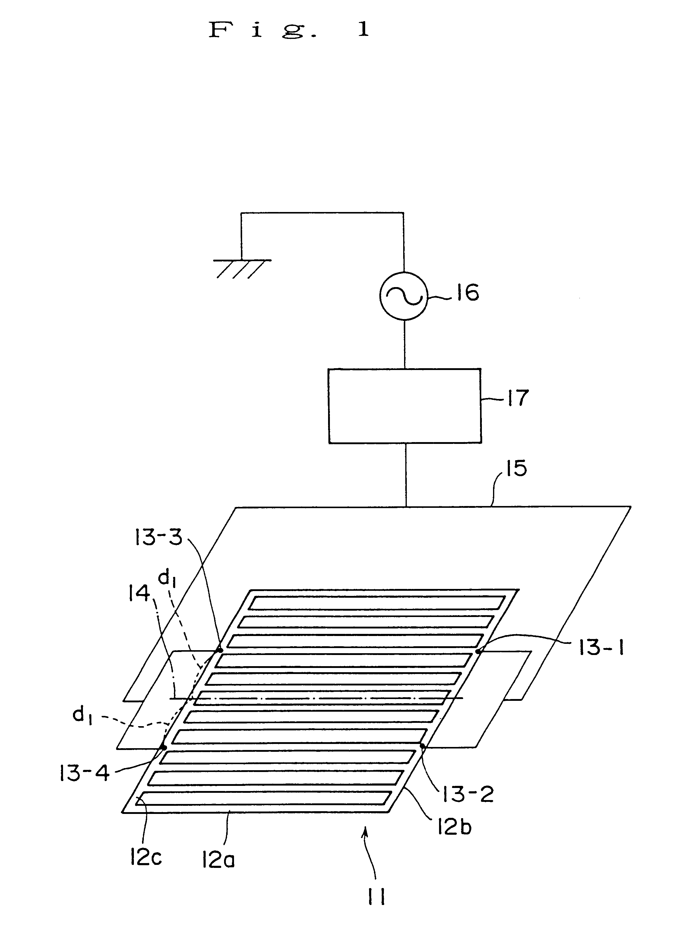
FIG. 1 is a conceptual diagram showing a first embodiment, which is a preferred embodiment of the first mode for carrying out the present invention.

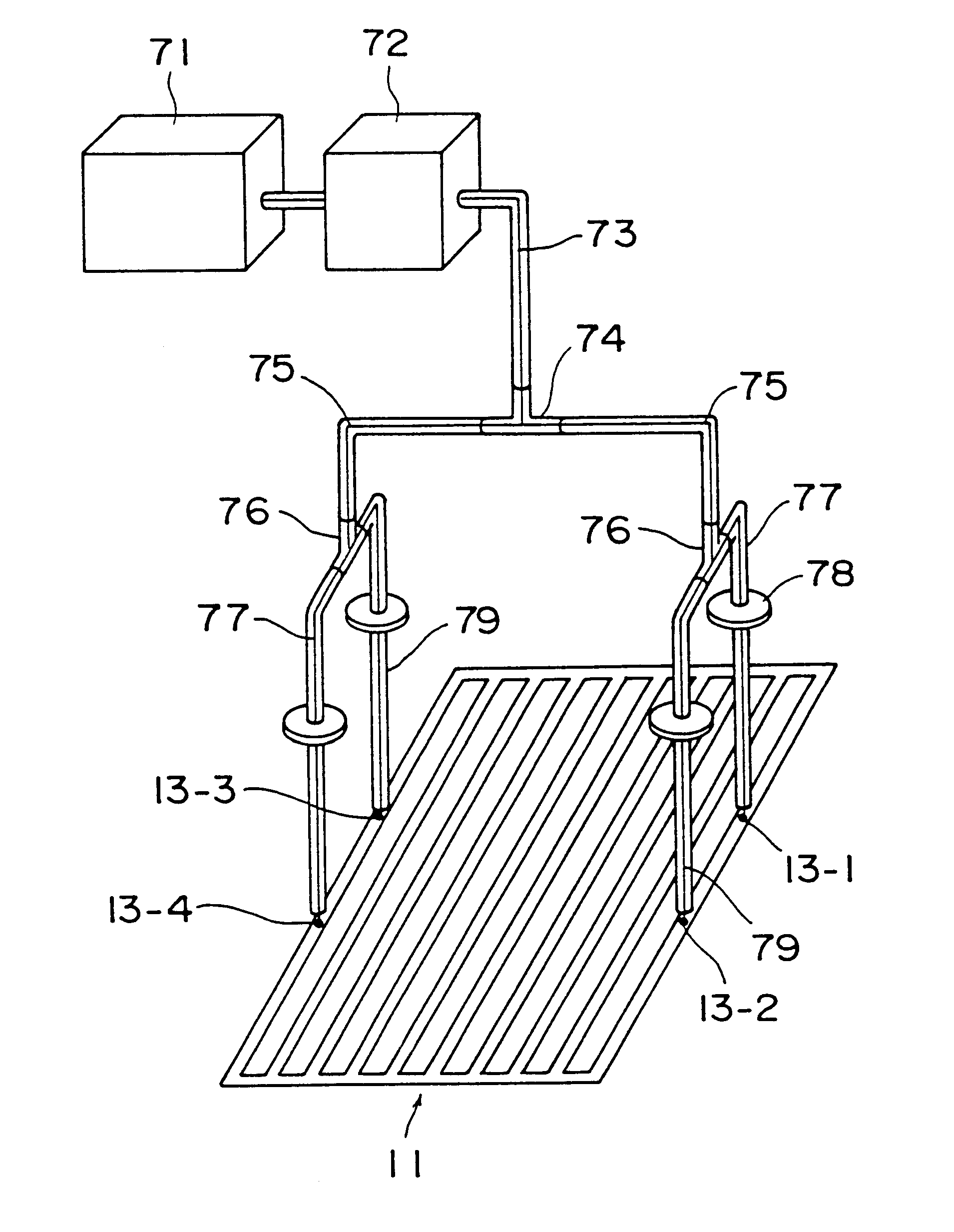
As shown in FIG. 1, a ladder electrode 11 of a vapor deposition apparatus according to the present embodiment is configured such that a plurality of electrode bars 12a are arranged in parallel with each other and such that electrode bars 12b and 12c are connected to the corresponding opposite ends of the electrode bars 12a, thereby forming a ladder-like electrode. Power supply points 13 (13-1 to 13-4) are arranged axisymmetrically with respect to a reference line 14, which is a bisector which bisects one side of the RF discharge electrode 11, while being spaced a predetermined distance from the reference line 14. RF power is supplied to the power supply points 13-1 to 13-4 from an RF power source 16 through a matching unit 17 and a coaxial cable 15 serving as a transmission line.

The RF power source 16 generates a VHF ba...

second embodiment

[Second Embodiment]

FIG. 3 shows a ladder electrode 11 according to a second embodiment, in which the ladder electrode shown in FIG. 1 is modified to a 2-point power supply apparatus. The second embodiment is a preferred embodiment of the first mode for carrying out the present invention. The ladder electrode 11 is similar to that of FIG. 1 except that a 2-point power supply apparatus is employed, and thus a description is omitted. FIG. 5 shows film deposition rate distribution as observed in depositing a film by use of the ladder electrode 11 of 2-point power supply shown in FIG. 3. As shown in FIG. 5, it was confirmed that a most portion of film deposition rate distribution on the substrate showed a uniformity of .+-.10%.

Although not illustrated, a larger electrode was tested while 8-point power supply was employed. In this case, even when the distance between a power supply point and a most distant point therefrom is 1 / 4 to 1 / 8 wavelength, uniform distribution was obtained.

When th...


PUM

PropertyMeasurementUnit
Timeaaaaaaaaaa
Angleaaaaaaaaaa
Diameteraaaaaaaaaa

Abstract

A plurality of electrode bars are arranged in parallel with each other, and side electrode bars are connected to the corresponding opposite ends of the electrode bars, thereby forming a ladder-like RF discharge electrode. Power supply points are arranged axisymmetrically with respect to a reference line, which is a bisector which bisects one side of the RF discharge electrode, while being spaced a predetermined distance from the reference line, thereby suppressing voltage distribution on the ladder electrode, which has an effect on uniformity of discharge distribution, to a sufficiently low level of nonuniformity. Thus, uniform distribution of film deposition rate can be obtained, thereby enabling uniform deposition even in large-area applications.

Description

1. Field of the InventionThe present invention relates to the form of a discharge electrode and a power supply method employed by an RF plasma generation apparatus for use in forming semiconductor films of amorphous silicon, microcrystalline silicon, polycrystalline silicon, silicon nitride, etc. to be used in solar cells, thin-film transistors, etc. as well as for use in etching such semiconductor films.2. Description of the Related ArtAs examples of the RF plasma generation apparatus, there will be described two structures used in a plasma-enhanced chemical vapor deposition apparatus (hereinafter called "PCVD" or a "vapor deposition apparatus") used conventionally to form thin films of amorphous silicon (hereinafter called "a-Si") and thin films of silicon nitride (hereinafter called "SiNx"); i.e., 1 a structure using a ladder electrode for exciting discharge; and 2 a structure using a parallel-plate electrode for exciting discharge.1 First, the structure using a ladder electrode ...

Claims


Application Information

Patent Timeline
IPC IPC(8): H01J37/32H05H1/46C23C16/50H01L21/205
CPCH01J37/32082H05H1/46H01J37/32532
Inventor YAMAKOSHI, HIDEOYAMAGUCHI, KENGOUMURATA, MASAYOSHITAKEUCHI, YOSHIAKINAWATA, YOSHIKAZUSATAKE, KOJIKOKAJI, SATOSHIMORITA, SHOJIHISATOME, MASATOSHIHORIOKA, TATSUJIMASHIMA, HIROSHI
Owner MITSUBISHI HEAVY IND LTD
Why Eureka
Try Eureka