Hydrocarbon separation process and apparatus

a technology of hydrocarbon separation and process, applied in the field of hydrocarbon separation process and apparatus, can solve the problems of uneconomically high power requirements, inability to use conventional overhead condensers, and inability to provide very high recovery of ethane, and achieve the effect of reducing overhead temperature and increasing recovery

Inactive Publication Date: 2002-04-02
COSTAIN OIL GAS & PROCESS
View PDF12 Cites 105 Cited by
  • Summary
  • Abstract
  • Description
  • Claims
  • Application Information

AI Technical Summary

Benefits of technology

By heat-exchanging the first liquid stream and the separated lights fraction with the expanded stream from (d), against the evaporating stream derived from the subcooled stream, a stream of lower temperature is produced that ultimately leads to reduced overheads temperature and increased recovery.

Problems solved by technology

Very high ethane recovery can therefore result in uneconomically high power requirements in either recompression of the residual vapour to required product pressure, external refrigeration to increase liquids condensation or in feed gas compression which also increases liquids condensation.
A conventional overhead condenser, condensing overhead vapour at column pressure, can not usually be utilised due to the absence of process streams at a lower temperature to provide the necessary refrigeration.
U.S. Pat. Nos. 4,171,964 and 4,157,904 describe processes in which streams relatively rich in ethane are sent to the top of the demethaniser to act as reflux, and thus do not provide very high recovery of ethane.
This configuration is less thermodynamically efficient than that of a standalone compressor, due to the losses inherent in warming and re-cooling the residue vapour.
At lower recycle stream pressures, compression power requirements are reduced, but the cooling curve becomes less linear and a pinch can occur which limits the temperature to which the recycle stream can be cooled.

Method used


Image

  • Hydrocarbon separation process and apparatus
  • Hydrocarbon separation process and apparatus
  • Hydrocarbon separation process and apparatus

Examples


embodiment 1

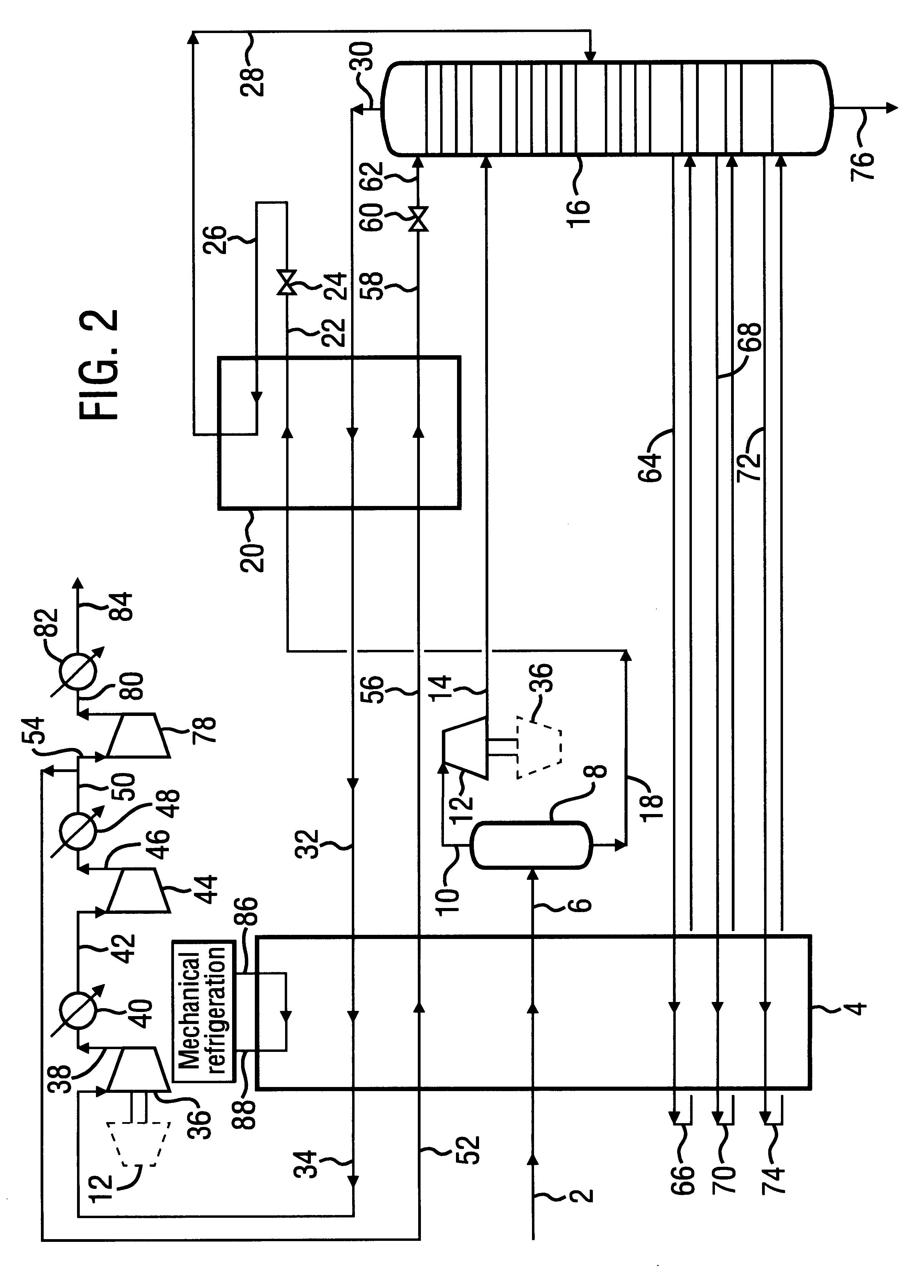
The invention is described below in terms of a process for high ethane recovery. The description should be read in conjunction with the flow diagram in FIG. 2.

A feed gas at an elevated pressure 2 is passed through heat exchange system 4 where it is cooled and partially condensed. The liquid phase 18 is separated from the uncondensed vapour phase 10 in vapour / liquid separator 8. A first gaseous stream comprising vapour 10 is work expanded in turbo-expander 12 to give a two phase stream 14 which is fed to the upper portion of a fractionation column in the form of demethaniser 16. A first liquid stream comprising liquid 18 is cooled in heat exchange system 20 to give sub-cooled liquid 22 which is expanded across valve 24 to give a stream 26 which may be liquid or two phase. Stream 26 is partially evaporated in heat exchange system 20 to give a two phase stream 28 which is fed to a mid-stage of the demethaniser 16.

Refrigeration for feed gas cooling is supplemented by evaporating liquid ...

embodiment 2

The second embodiment of the invention is described below in terms of a process for high ethane recovery. The description should be read in conjunction with the flow diagram in FIG. 5.

A feed gas at an elevated pressure 2 is passed through heat exchange system 4 where it is cooled and partially condensed to give a two phase stream 6. The liquid phase 48 is separated from the uncondensed vapour phase 10 in vapour / liquid separator 8. The first gaseous stream comprising vapour 10 is work expanded in turbo-expander 12 to give a two phase stream 14 which is fed to a mid point of a reequilibration device in the form of high pressure wash column 16. A first liquid stream comprising liquid 48 is expanded to a medium pressure across valve 50 to give a two phase stream 52 which is fed to the bottom of the high pressure wash column 16.

Refrigeration for feed gas cooling is supplemented by evaporating liquid refrigerant stream 108 in heat exchange system 4 giving refrigerant vapour stream 110. Us...


PUM

PropertyMeasurementUnit
liquidaaaaaaaaaa
heataaaaaaaaaa
pressureaaaaaaaaaa

Abstract

A process is described for separating the heavier hydrocarbons from a gaseous hydrocarbon feed wherein a first separator is employed to separate partially condensed gaseous feed and wherein the vapour portion undergoes work expansion and is fed to a fractionation column. The liquid portion is subcooled in heat exchange with the overhead vapour from the fractionation column, expanded, evaporated to provide refrigeration at a low temperature level, and fed to the fractionation column. The rewarmed residual vapour is subsequently compressed to a pressure suitable for export, with a portion of the compressed gas being cooled, condensed and recycled back to reflux the top section of the fractionation column.Also described is a process wherein a first separator is employed to separate partially condensed gaseous feed and wherein the vapour portion undergoes work expansion and is fed to a high pressure wash column. The liquid portion is expanded and fed to the base of the high pressure wash column. Bottoms liquid from the wash column is subcooled in heat exchange with the overhead vapour from a fractionation column, expanded, evaporated to provide refrigeration at a low temperature level, and fed to the fractionation column. Vapour from the high pressure wash column is partially condensed, with the liquid portion used to provide reflux to the high pressure wash column and the fractionation column.The processes are especially applicable to recovery of ethane and heavier components from natural gas. Overall process power requirements are reduced, recovery of the desired heavy hydrocarbons is increased or both of these effects are realised.

Description

INTRODUCTION AND BACKGROUNDThis invention relates to a process, and the apparatus for effecting such a process, for the cryogenic fractionation of gaseous hydrocarbon feeds to extract and recover the valuable heavier components thereof. The invention is particularly concerned with a process for high recovery of ethane and heavier components from a natural gas feed. The process is not limited to the recovery of paraffinic compounds such as ethane found in natural gas, but also, for example, to olefins such as ethylene often found in gases associated with petroleum refining or petrochemicals manufacture.Conventional processes to effect very high recovery of ethane and heavier components from natural gas typically utilise a combination of heat exchange, turbo-expansion, phase separation and fractionation steps. The use of turbo-expansion produces work, which can be used to drive a compressor to supplement residual gas compression, and by removing energy from the feed gas produces low t...

Claims


Application Information

Patent Timeline
Patent Type & Authority Patents(United States)
IPC IPC(8): C07C7/00F25J3/02
CPCC07C7/005F25J3/0209F25J3/0219F25J3/0233F25J3/0238C10G5/06F25J2270/90F25J2200/02F25J2200/04F25J2200/74F25J2200/76F25J2200/78F25J2205/04F25J2210/12F25J2230/60F25J2240/02F25J2245/02F25J2270/02
Inventor FINN, ADRIAN JOSEPHJOHNSON, GRANT LEIGH
Owner COSTAIN OIL GAS & PROCESS
Why Eureka
Try Eureka