
Enclosure for electrical components installed in locations where a flammable gas or vapor is expected to be present

a technology for electrical components and enclosures, which is applied in the direction of cell components, casings/cabinets/drawers, electrical apparatus casings/cabinets/drawers, etc., can solve the problems of flammable fluid penetration into the interior of the enclosure of electrical components, defects in the seal or misalignment of the seal, etc., to reduce the concentration of flammable fluid, reduce the likelihood of flammable fluid being ignited, and the effect of reducing

Inactive Publication Date: 2002-04-16
DAIMLER AG
View PDF28 Cites 34 Cited by
  • Summary
  • Abstract
  • Description
  • Claims
  • Application Information

AI Technical Summary

Benefits of technology

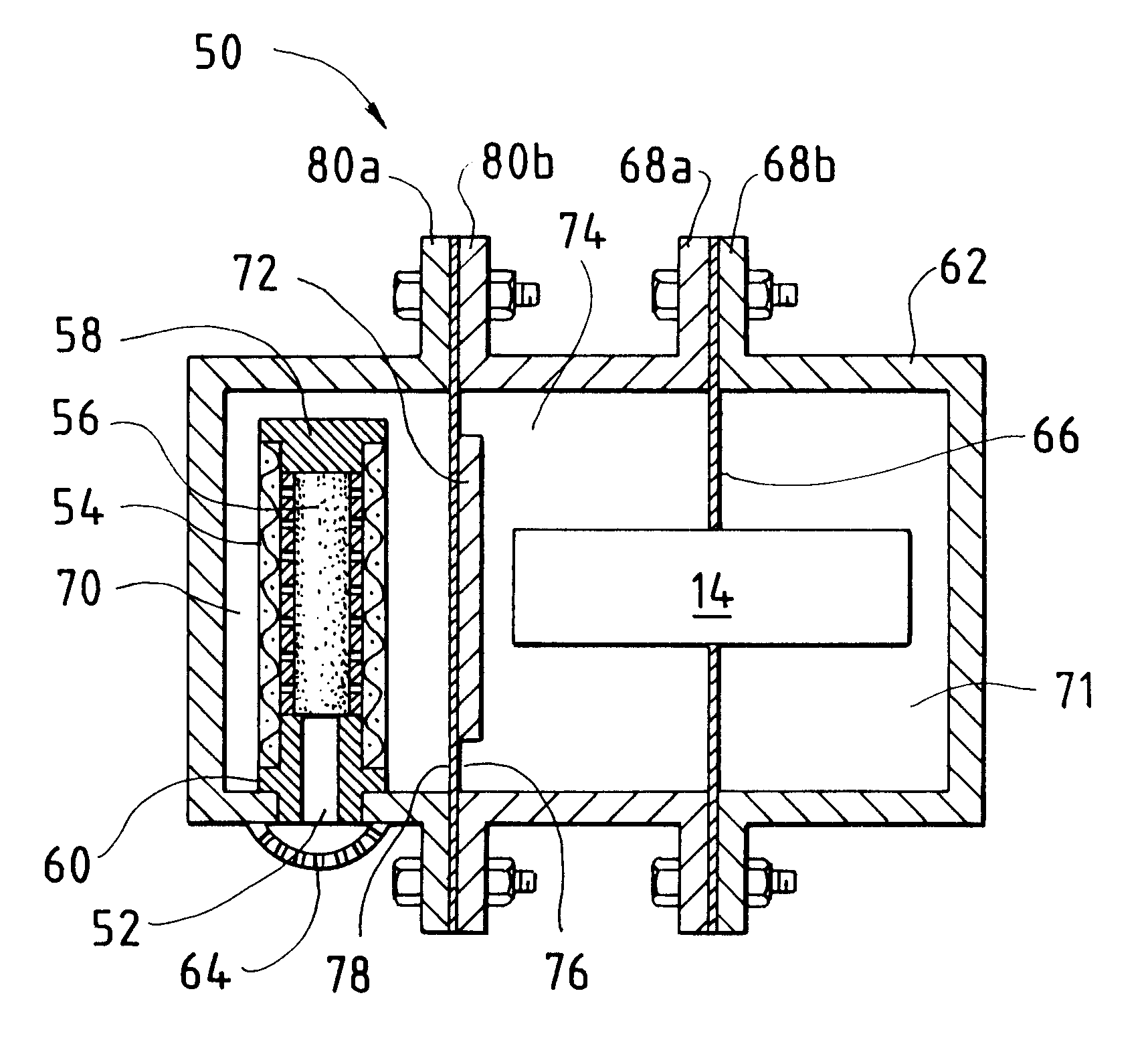
The enclosure housing preferably comprises at least two pieces which cooperate to form the housing. Preferably, the housing pieces may be separated so that electrical components contained within the housing may be accessed and / or serviced. To reduce the weight and cost of the enclosure, the protective housing pieces may be made from a thermoplastic material. Alternatively, the protective housing pieces may be made from steel or aluminum or any other suitable housing materials.
An advantage of the present enclosure is that, unlike flame-proof enclosures, the present enclosure need not be constructed to withstand an internal explosion because the catalyst prevents a combustible concentration of flammable fluid from accumulating within the enclosure housing. Thus, the present enclosure may utilize thinner and lighter housing pieces, compared to an equivalent flame-proof enclosure housing made from the same materials.
The disclosed electrical component enclosures are designed to reduce the concentration of a flammable fluid that may accumulate within the enclosure, thereby reducing the likelihood of the flammable fluid being ignited. Accordingly, the present enclosures need not be designed to withstand an internal explosion. Thus an electrical component enclosure is provided that may be made smaller, lighter, and less expensive compared to a conventional flame-proof enclosure that would be acceptable for the same use.

Problems solved by technology

However, gasketed or "sealed" enclosures can not guarantee complete sealing against the penetration of flammable gases by diffusion.
There may also be other causes for flammable fluid penetration into the interior of an electrical component enclosure, such as, for example, defects in the seal or misalignment of the seals.
Furthermore, in addition to flammable fluids which may originate from the atmosphere surrounding the enclosure, flammable fluids may also originate inside the enclosure from electrical components themselves, such as, for example, electrochemical fuel cells.
However, a problem with flame-proof enclosures is that because they are made to withstand an internal explosion, they are heavy, physically large, and relatively expensive.
Another problem is that, while flame-proof enclosures may contain the explosion, they do not prevent an explosion.
Restricted breathing enclosures may not be permitted where there may be exposure to flammable fluids such as hydrogen or acetylene which have a high diffusion rates.
A problem with conventional restricted breathing enclosures is that if a concentration of a flammable fluid does accumulate inside the enclosure, there is no mechanism for reducing the concentration of the accumulated flammable fluid.

Method used


Image

  • Enclosure for electrical components installed in locations where a flammable gas or vapor is expected to be present
  • Enclosure for electrical components installed in locations where a flammable gas or vapor is expected to be present
  • Enclosure for electrical components installed in locations where a flammable gas or vapor is expected to be present

Examples


Embodiment Construction

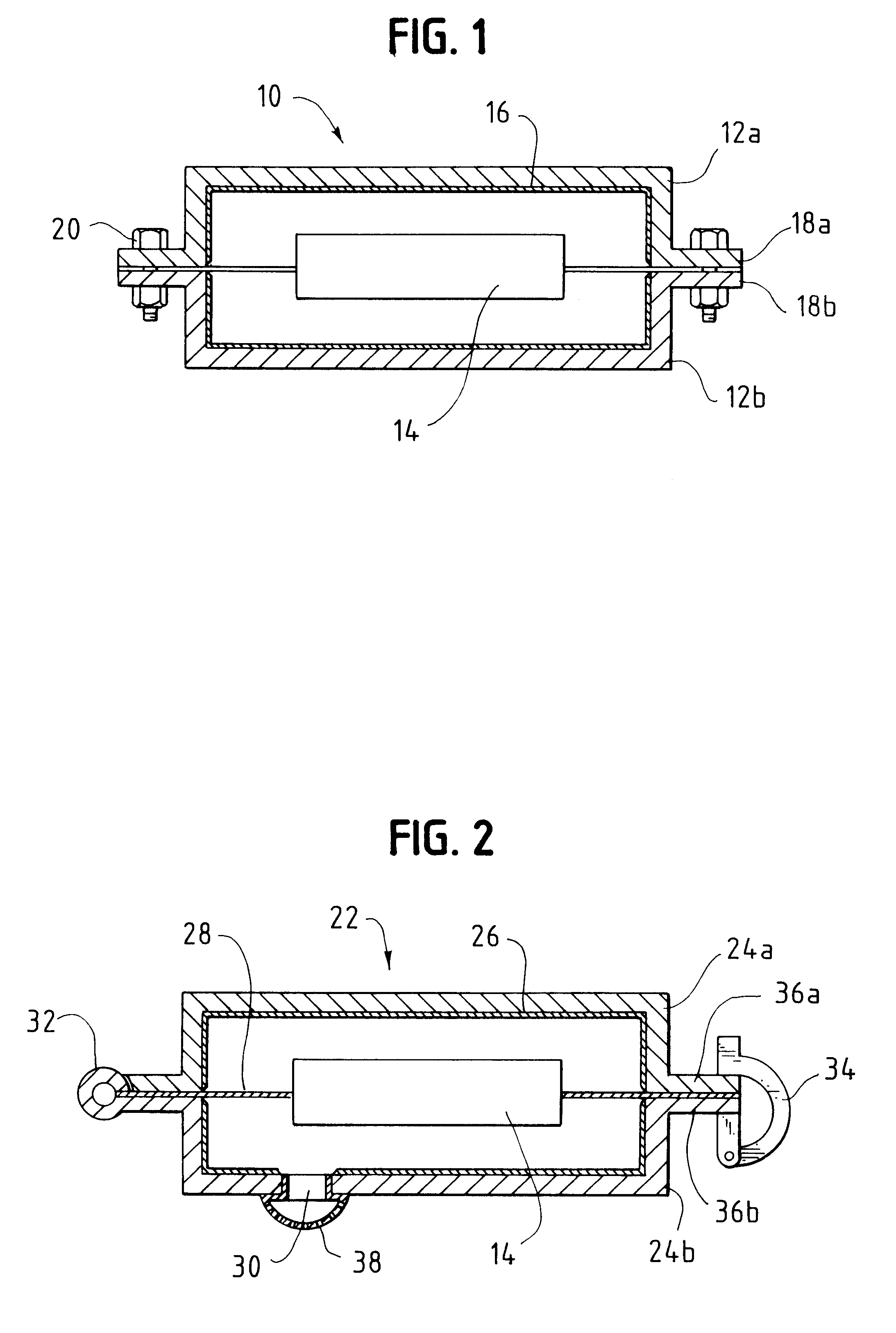
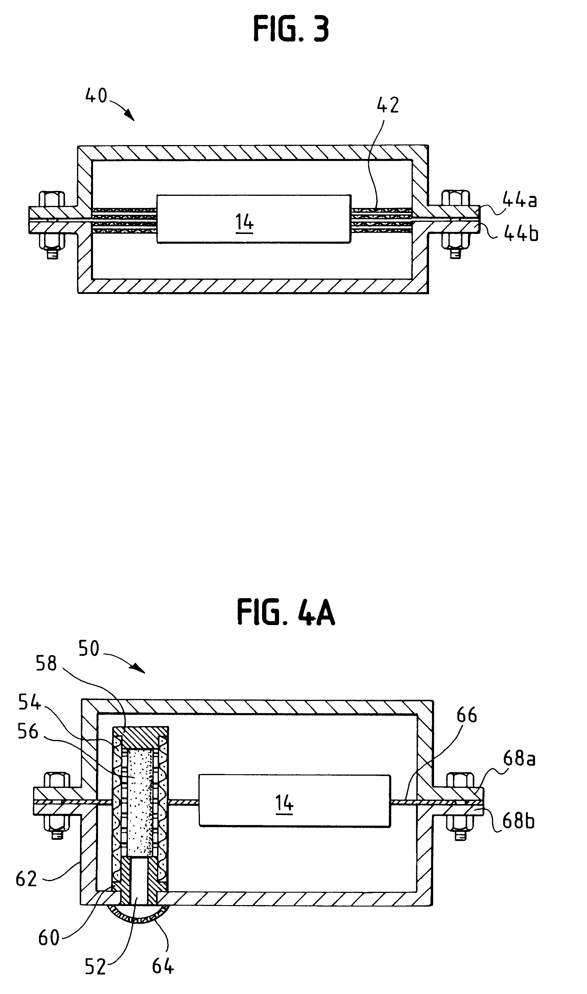
FIG. 1 is a schematic cross sectional view of an electrical component enclosure 10. In this preferred embodiment, enclosure 10 comprises a housing 12 having two pieces 12a and 12b. Electrical component 14 may be, for example, a switch, a motor starter, a motor, an electrical panel board, an electrochemical fuel cell, or other electrical component which needs protection.

Coating 16 is disposed on interior surfaces of housing pieces 12a and 12b. Coating 16 comprises a catalyst for inducing a flammable fluid to react to produce a non-flammable product. In a preferred embodiment, for use in the presence of hydrogen and oxygen gas mixtures, the catalyst is a wet-proof platinum catalyst, mixed in a zeolite (clay) and polymeric binder that is applied like a paint, using a sprayer or brush. In this embodiment, hydrogen is induced by the catalyst to react with the oxygen to produce water. Because water is a product of this reaction, water may be present near the catalyst. Accordingly, the pre...


PUM


Abstract

The present invention provides an electrical component enclosure for installation in a location where a flammable gas or vapor is expected to be present. The electrical component enclosure incorporates a catalyst for inducing a reaction to convert a flammable fluid to a non-flammable product, thereby reducing the flammable fluid concentration and reducing the likelihood of the flammable fluid being ignited. The enclosure preferably permits the free exchange of gas and vapor between the surrounding atmosphere and the enclosure interior.

Description

FIELD OF THE INVENTIONThe present invention provides an enclosure for protecting electrical components installed in a location where a flammable gas or vapor is expected to be present.BACKGROUND OF THE INVENTIONEnclosures may be used to provide protection for an electrical component such as, for example, an electrical switch, a motor starter, a motor, or an electrochemical fuel cell. These enclosures are typically accessible by opening so that the electrical component placed within the enclosure housing may be accessed and / or serviced. Thus enclosure housings typically comprise at least two pieces that fit together to provide a protective enclosure around the electrical component. In addition to protecting the electrical component against physical damage, in locations where a flammable gas or vapor may be present, it is also desirable for the enclosure to protect the electrical component from exposure to combustible concentrations of the flammable gas or vapor which the electrical c...

Claims


Application Information

Patent Timeline
IPC IPC(8): H01M2/10H02K5/12H02K5/136H01M8/24
CPCH01M2/10H02K5/136H01M8/247Y02E60/50Y02E60/10
Inventor KNAGGS, L. BRENON
Owner DAIMLER AG
Learn More