Surface acoustic wave transducer using NSPUDT property substrate and surface acoustic wave filter using the transducer

a surface acoustic wave and transducer technology, applied in piezoelectric/electrostrictive/magnetostrictive devices, piezoelectric/electrostriction/magnetostriction machines, electrical equipment, etc., can solve the problem of difficult to obtain unidirectional transducers whose forward directions are difficult to obtain, and the design and manufacturing process is complicated

Inactive Publication Date: 2002-04-16
NGK INSULATORS LTD +2
View PDF15 Cites 5 Cited by
  • Summary
  • Abstract
  • Description
  • Claims
  • Application Information

AI Technical Summary

Benefits of technology

Furthermore, in case of using an anisotropic substrate such as Li.sub.2 B.sub.4 O.sub.7 substrate having a cut angle, represented by Euler's angle, of .phi.=0.degree., .theta.=51.degree. and .phi.=90.degree., in said substrate a phase rotation of -45.degree. being produced by the reflection, since the phase shift of .lambda. / 8 is introduced in a direction opposite to the orientation of the substrate, when a distance between the exciting electrode structure and the reflector structure is set to (2n+1).lambda. / 4 (n being a positive integer), a surface acoustic wave emitted by the exciting electrode structure in a direction opposite to the operating direction of the NSPUDT property has same phase with a surface acoustic wave reflected by the reflector structure. In this manner, it is also possible to realize the transducer having the reversed directivity. In case of forming the transversal type surface acoustic wave filter by providing the transmitter side transducer and receiver side transducer on a piezoelectric substrate, both the transmitter and receiver side transducers may be formed by one and same electrode material, and thus a manufacturing process becomes much simpler.

Problems solved by technology

In accordance with an increase in an operating frequency, said dimensions become extremely small, and it is difficult to manufacture accurately the electrodes having the desired dimensions.
However, in the surface acoustic wave device utilizing the above mentioned NSPUDT, since the anisotropy of the substrate itself is utilized, there is a problem that it is difficult to obtain unidirectional transducers whose forward directions are opposed to each other, one for the output side, i.e. transmitter side transducer and the other for the input side, i.e. receiver side transducer.
However, according to the generally used manufacturing process, the formation of electrodes from different electrode materials and the embedded electrodes might cause the complication in the designing and manufacturing and high cost, and thus it would be difficult to obtain a desired accuracy, so that the desired frequency and phase characteristics could not be attained.
Further, in case of using the NSPUDT substrate having a large reflection coefficient of electrode fingers, the reflecting effect of the electrodes fingers might become too strong to control a transduction characteristic.
If this known arrangement is applied to the anisotropic substrate having the NSPUDT behavior, it would be impossible to utilize the reflection effect efficiently to realize a practical transducer.

Method used


Image

  • Surface acoustic wave transducer using NSPUDT property substrate and surface acoustic wave filter using the transducer
  • Surface acoustic wave transducer using NSPUDT property substrate and surface acoustic wave filter using the transducer
  • Surface acoustic wave transducer using NSPUDT property substrate and surface acoustic wave filter using the transducer

Examples


first embodiment

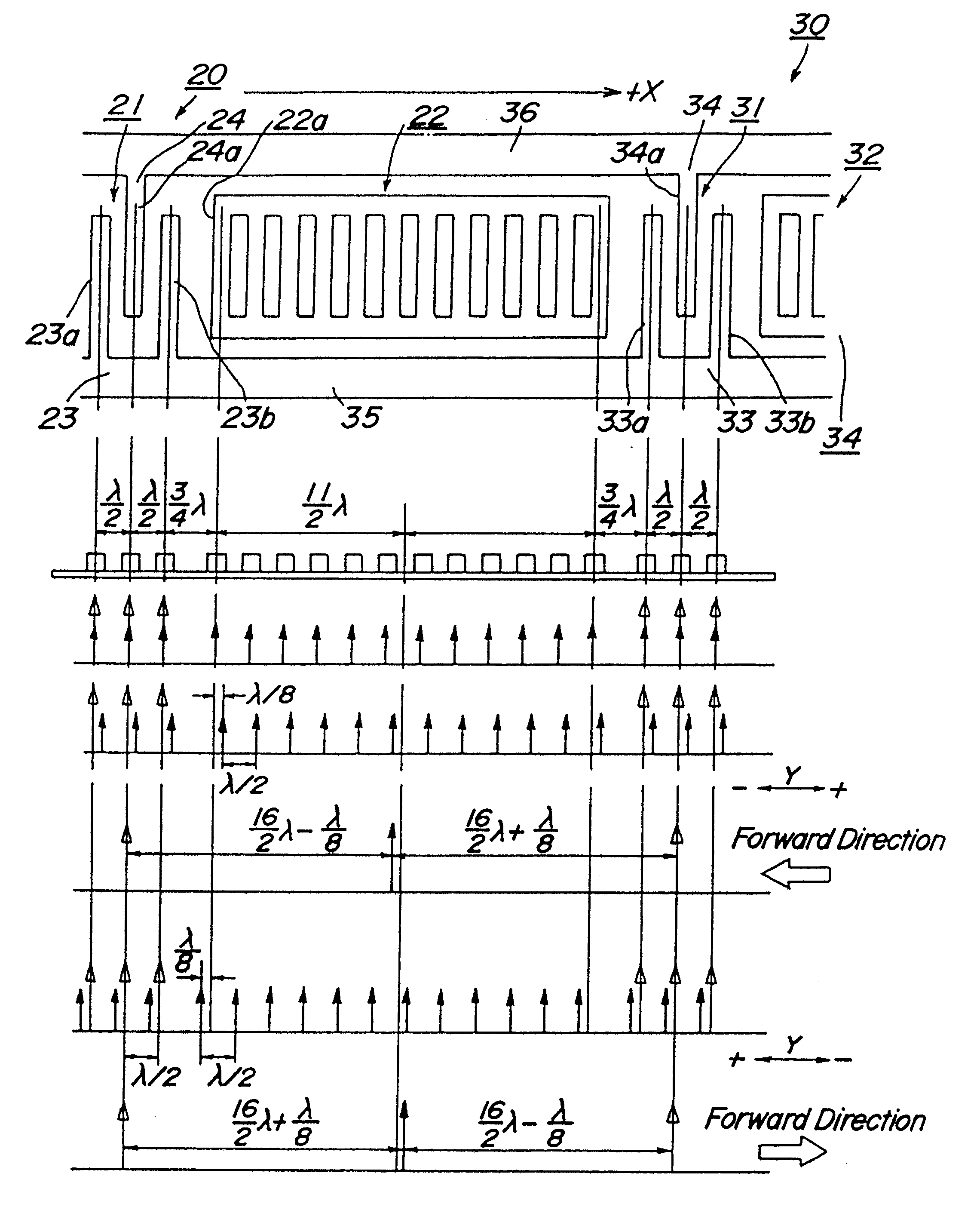
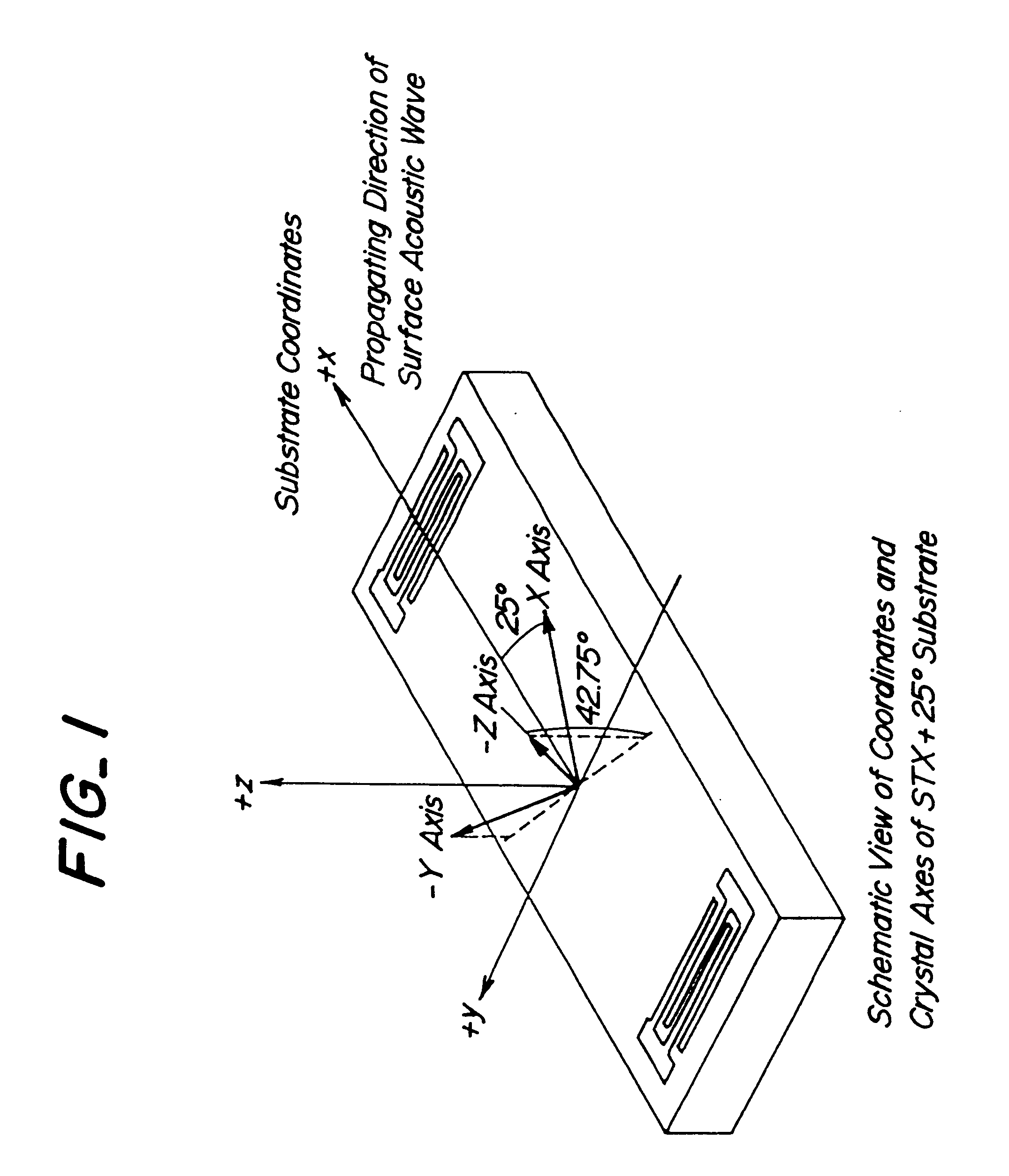
FIG. 5 is schematic views showing the electrode structure and operations of the surface acoustic wave transducer according to the invention. In this embodiment, an STX+25.degree. cut quartz substrate is used as the substrate showing the NSPUDT behavior. The transducer of the present embodiment comprises such a construction that a plurality of transducer structure pairs each including an exciting electrode structure and a reflector structure are aligned along the operating direction of the surface acoustic wave due to the NSPUDT property of the substrate. It should be noted that for the sake of clarity, only a portion including two pairs of the transducer structures is shown in the drawing. A positive direction of an operating direction due to the NSPUDT property of the substrate is denoted by an arrow +X. An operating direction due to the NSPUDT property specific to the anisotropic substrate denoted by an arrow Y is obtained when the normal type electrode of .lambda. / 4 is formed on ...

second embodiment

FIG. 6 depicts the surface acoustic wave transducer according to the invention. The transducer of the present embodiment has basically the same electrode structure, but the numbers of respective exciting electrode structures and reflector structures differ from those of the electrode structure shown in FIG. 5. The effect of the reflection due to the electrode fingers may be considered to be identical for both the exciting electrode and reflector electrode. Since respective electrode fingers are formed at a pitch of .lambda. / 2, the reflection effect by the electrode fingers may be considered to be equivalent to a sum of reflection effects of respective electrode fingers. The reflection effect by the electrode fingers of the exciting electrode structure intensify the surface acoustic wave excited in the operating direction due to the NSPUDT property, but decreases the surface acoustic wave excited in the negative direction opposite to the operating direction. In the transducer shown i...

third embodiment

FIG. 15 is a schematic view depicting the surface acoustic wave filter according to the invention. In the present embodiment, the substrate is formed by the Li.sub.2 B.sub.4 O.sub.7 substrate in which the reflected surface acoustic wave is subjected to the phase rotation of -45.degree.. The transducer with the non-reversed directivity shown in FIG. 6 is used as a transmitter side transducer 60, and the transducer with the reversed directivity illustrated in FIG. 5 is used as a receiver side transducer 61. These transmitter and receiver side transducers have the basically same electrode structure, but the number of electrode fingers of the exciting electrode structure and the number of electrode fingers of the reflector structure are different for the transmitter side and receiver side. Therefore, the electrode fingers of the transmitter and receiver side transducers may be formed at the same pitch, and thus the manufacturing precision can be further improved.

FIG. 16 is a schematic v...


PUM


Abstract

In order to provide a transducer suitable for an anisotropic substrate having the NSPUDT property, on the anisotropic piezoelectric substrate being cut to have the NSPUDT property, there is formed a transducer structure having an exciting electrode structure (21) and a reflector structure (22). When lambd is a wavelength of a fundamental surface acoustic wave, said exciting electrode structure (21) includes a positive electrode (23) having a plurality of electrode fingers arranged at a pitch lambd and a negative electrode (24) having at least one electrode finger interdigitally arranged between said electrode fingers of the positive electrode with a center distance of lambd / 2. The reflector transducer (22) includes a plurality of electrode fingers arranged with a center distance of lambd / 2, and a distance Lg between said exciting electrode structure (21) and the reflector structure (22) is set to Lg=(2n+1)lambd / 4 (n being a positive integer).

Description

The present invention relates to a surface acoustic wave transducer for use in a surface acoustic wave device such as a SAW filter and a SAW resonator, and more particularly to a surface acoustic wave transducer comprising a piezoelectric substrate having a natural single-phase unidirectional transducer (termed as NSPUDT) property and an electrode structure having a directivity. The present invention also relates to a surface acoustic wave filter having such a transducer.TECHNICAL BACKGROUNDHeretofore, there has been widely used a transversal type SAW filter, in which on a surface of a piezoelectric substrate, are arranged a transmitter side transducer including interdigitally arranged positive and negative electrodes to be connected to two output terminals of a single phase signal source having a phase difference of 180.degree., and a receiver side transducer also including interdigitally arranged positive and negative electrodes, said transmitter and receiver side transducers bein...

Claims


Application Information

Patent Timeline
Patent Type & Authority Patents(United States)
IPC IPC(8): H03H9/145H03H9/25H03H9/64
CPCH03H9/02716H03H9/14505H03H9/14594H03H9/14547H03H9/14552H03H9/14517H03H9/64
Inventor TAKEUCHI, MASAOYAMANOUCHI, KAZUHIKOODAGAWA, HIROYUKITANAKA, MITSUHIRO
Owner NGK INSULATORS LTD
Why Eureka
Try Eureka