Acoustic standing-wave enhancement of a fiber-optic salmonella biosensor

a biosensor and fiber-optic technology, applied in the field of fiber-optic biosensors, can solve the problems of destroying formation and limited intensity

Inactive Publication Date: 2002-05-21
BOARD OF GOVERNORS FOR HIGHER EDUCATION STATE OF RHODE ISLAND & PROVIDENCE PLANTATIONS
View PDF3 Cites 67 Cited by
  • Summary
  • Abstract
  • Description
  • Claims
  • Application Information

AI Technical Summary

Problems solved by technology

The intensity is limited, however, by the generation of cavitation and streaming, which destroy the formations.

Method used


Image

  • Acoustic standing-wave enhancement of a fiber-optic salmonella biosensor
  • Acoustic standing-wave enhancement of a fiber-optic salmonella biosensor
  • Acoustic standing-wave enhancement of a fiber-optic salmonella biosensor

Examples


Embodiment Construction

)

Fiber-Optic Fluorescence Detection System

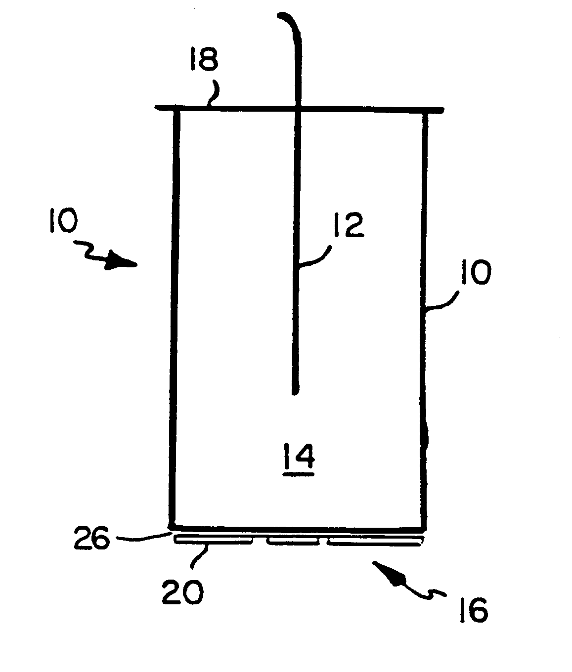
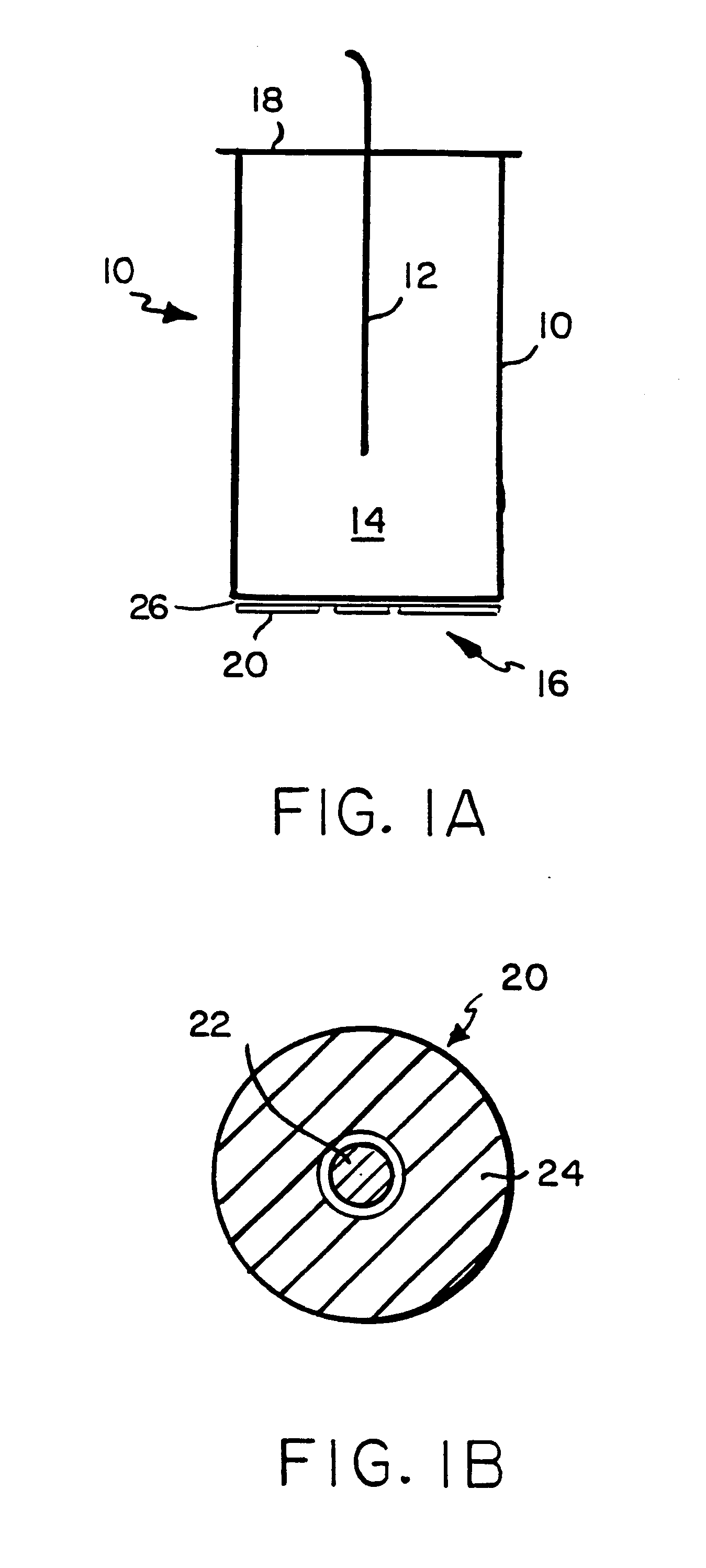
Referring to FIG. 1, a cylindrical test cell 10 is shown with a fiber tip 12 inserted into media 14 in the cell 10. A transducer 16 is located at the bottom of the cell and a reflecting plate 18 is located at the top of the cell. A single step-tapered fiber 12 is used for excitation and detection. The sensing fiber is located along the axis of the cell. The electrode plating of the transducer is indicated. The beam is from a diode laser (.lambda.=650 nm) focused into one branch of a 300-.mu.m 2.times.2 coupler, one branch of which is connected to the sensing fiber. The sensing fiber is fused silica with a 300-.mu.m core diameter, obtained from 3M Corp. The tip of the sensing fiber 10, which has had its cladding removed and its core diameter reduced in three steps from 300 to 40 .mu.m over a length of 20 mm, is inserted into a test cell 12. The tip and fiber optic sensing system are described in detail in our co-pending application Ser. No. 0...


PUM

PropertyMeasurementUnit
lengthaaaaaaaaaa
lengthaaaaaaaaaa
excitation wavelengthaaaaaaaaaa

Abstract

A fluorescent fiber-optic biosensor system using ultrasonic concentration of particles and cells for the detection of Salmonella typhimurium. A biosensor test chamber serves as an ultrasonic standing-wave cell that allows microspheres or cells to be concentrated in parallel layers or in a column along the axis of the cell. A fiber probe along the axis delivers laser excitation to fluorescent-labeled antibodies of Salmonella and collects the fluorescent signal. The Salmonella-antibody complexes are moved acoustically to the axis of the cell, increasing the fluorescent signal. Alternatively, the Salmonella-labelled antibody complexes attach to unlabeled antibodies that have been immobilized on the surface of polystyrene microspheres. This entire structure can be manipulated acoustically and the increase in the fluorescent signal, which can be an order of magnitude, indicates the presence of Salmonella.

Description

1. Field of the InventionA fiber-optic biosensor detects pathogens based on immunoassay. Acoustic Enhancement concentrates the bound antibody enhancing detection.2. Description of the Relevant ArtSensitive detection of fluorescence or luminescence from biological reaction in vivo is important for many biosensor applications. Considerable effect has been devoted to the development of fiber-optic fluorescent biosensors because of their potential sensitivity, detection speed, and applicability to a wide variety of assay conditions.Fiber-optic fluorescent immunosensors require that the dye molecules, which indicate unambiguously the presence of the antigen, find their way to the optically active region of the fiber. This can be accomplished by immobilizing the capture antibodies directly on the tip or the tapered core of the fiber, but this means that the capture process is localized and that several rinsing steps are needed to avoid ambiguity and to recycle the system for another measu...

Claims


Application Information

Patent Timeline
Patent Type & Authority Patents(United States)
IPC IPC(8): G01N33/543G01N33/569
CPCG01N33/54373G01N33/56916Y10S436/805Y10S435/808G01N2333/255
Inventor LETCHER, STEPHEN V.RAND, A. GARTHZHOU, CHONGHUA
Owner BOARD OF GOVERNORS FOR HIGHER EDUCATION STATE OF RHODE ISLAND & PROVIDENCE PLANTATIONS
Why Eureka
Try Eureka