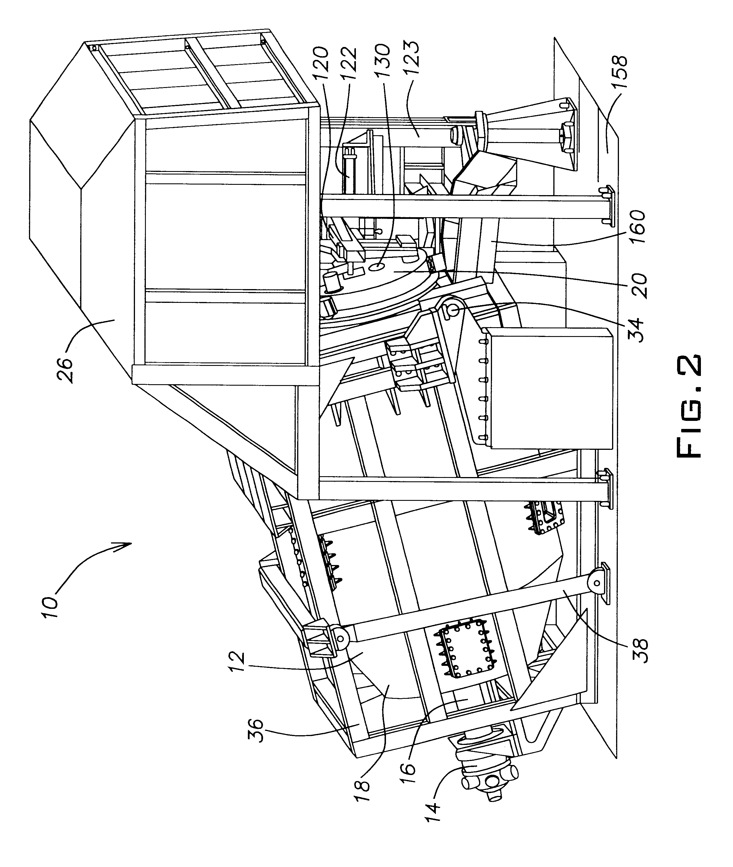
The door 20 assists in holding and orienting the burner 28. The burner 28 may also be held by a connection to the stanchion 123. The door 20 also helps to regulate the
atmosphere in the furnace chamber 12. More specifically, the door reduces the free air and amount of
oxygen in the refractory chamber 46 below that which would otherwise be introduced in a doorless furnace system. Since little
oxygen is present, aluminum
oxide is less likely to form and the amount of flux can be reduced. In one embodiment, the burner opening 130 is located in approximately the center of the door 20. However, in order to achieve the heat
radiation pattern described below, the burner opening 130 can be positioned at any point on the door 20 in order to provide the desired angle and point of introduction of the
flame 150. For example, the opening can be located approximately half way between the left hand most point on the door and the center of the door. The tip of the burner 28 is inserted into the furnace chamber 12 a distance
ranging from being even with or adjacent the door to the longitudinal center of the furnace chamber 12. In one embodiment, the burner 28 traverses the inlet passage 22 so that the tip of the burner is located in the second end section 54 of the furnace chamber 12.
The paddles 62 are used to mix and agitate the charge material 148. The paddles 62 have various effects on the charge material 148 depending on which stage of operation (e.g., regions A-G in FIG. 9) the furnace system 10 is in. During the time period relating to region A, the paddles 62 mix the aluminum scrap (or
dross) and the flux material. It is noted that the geometric shaped surfaces of the refractory chamber 46 also assist in mixing and agitating the charge material 148 during all stages of operation. As the aluminum begins to melt during period B, salt
slag and oxidized aluminum, or aluminum
oxide (AlO.sub.2 and / or ALO.sub.3), begin to rise to the top of the charge material 148. The salt
slag and the aluminum
oxide are thermal insulators which will reduce the amount of heat transferred to the unmelted and plastic aluminum located under the top surface 156 where the salt
slag and aluminum oxide have formed a covering layer. As the furnace chamber 12 rotates, however, the paddles 62 will engage the top surface 156, breaking up and pushing down portions of the slag material and aluminum oxide formed at the top surface 156. By breaking up and submerging portions of the slag and aluminum oxide, better
heat transfer into the aluminum contained in the charge material 148 can be accomplished. An additional benefit is gained from submerging aluminum oxide as it is forming. The production of aluminum oxide from aluminum and
oxygen is an
exothermic reaction. Although the production of aluminum oxide is generally not desired as it lowers the amount of recovered aluminum, some aluminum oxide is bound to form and the heat generated by this
exothermic reaction can be used to help melt unmelted aluminum in the charge material 148 and increase the temperature of the charge material 148 as a whole. It is recognized that much of the heat generated in the production of aluminum oxide will escape from the furnace chamber 12 through the
flue opening 126, but at least a portion of the heat given off by this reaction may be harnessed by breaking up and submerging the aluminum oxide by the paddles 62. In addition, this submerging action assists to control the formation of additional aluminum oxide since the charge material 148 will act as a
heat sink drawing heat from aluminum that may be approaching the point of oxidizing.
After the charge material 148 becomes flowable in period C, the furnace system 10 is charged with another load of aluminum scrap (or dross) and flux. Solids 162 contained in the second charge will have a tendency to float at the top surface 156 of the charge material 148. During periods C and D, voids will temporarily form behind the paddles 62 as the paddles 62 engage and turn through the charge material 148 as a result of their rotation. The solids 162 will have a tendency to fall into the voids and become submerged in the charge material 148 when the voids fill with flowable charge material. The paddles 62 will also have a tendency to push solids 162 located in their path under the top surface 156 of the charge material 148. By submerging the solids 162, the already flowable charge material 148 can contact more surface area on the solids 162 and the solids 162 will act as a
heat sink, thereby conducting
heat energy from the charge material and melting more rapidly. Additionally, during periods D and F of the furnace operation, the paddles 62 act as they did during period B. During period E, the paddles act as they did during period C. Another reason for submerging solids 162 is to minimize
exposure of the solids 162 to the
flame 150 and to oxygen. The overall result of the paddles is to decrease the melt
cycle time, lower the amount of flux required to protect the aluminum from oxidizing and increase the percentage of aluminum recovered.
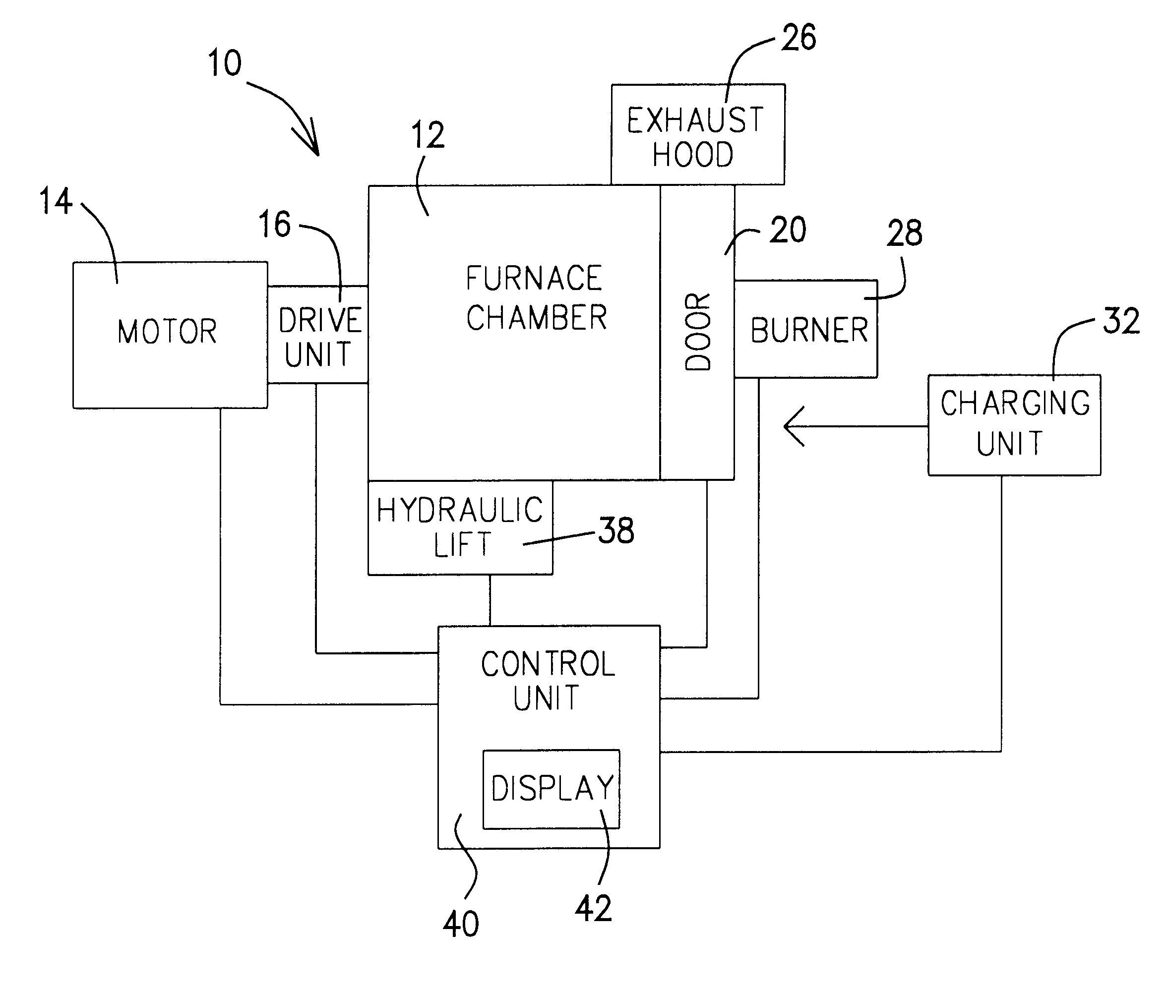
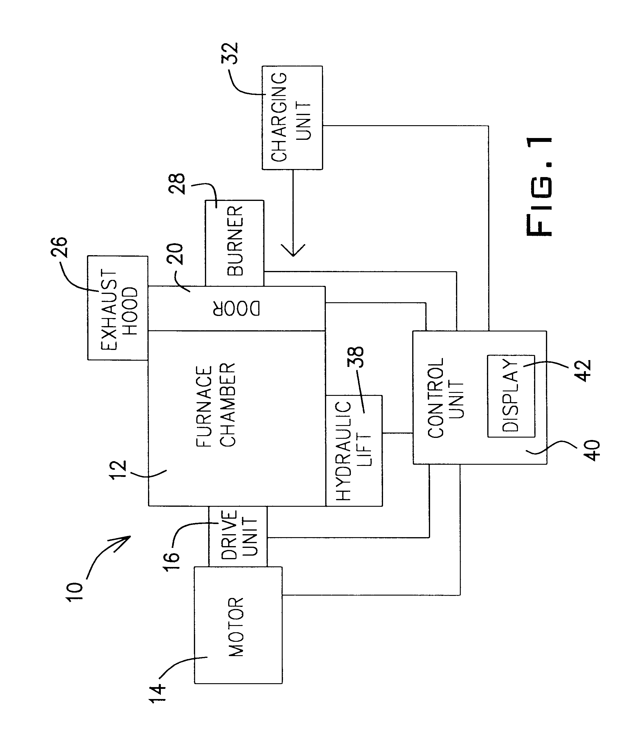
As mentioned above, the
control unit 40 controls the firing of the burner 28. The control of the burner 28 is a programmable feature. The
control unit 40 controls the quantity of fuel burned, the oxygen / fuel ratio, and the rate the oxygen and fuel are supplied to the burner 28. The quantity of fuel provided to the burner 28 is in direct correlation to the energy consumed by the furnace system 10. Therefore, computer modeling supplemented with actual
performance results of the furnace system 10 is used to establish a set of
energy consumption baselines per
ton of material processed. Alternatively, past
performance results are used to derive the
energy consumption baselines per
ton of material processed, without the assistance of computer modeling. This knowledge is used to develop a look-up table to indicate how much energy will be required to successfully process a given quantity of aluminum scrap (or dross) and a given quantity of flux. This allows the operator to specify the amount (e.g., weight) of scrap (or dross) and the amount of flux, plus the nature of the scrap or dross (e.g., painted or oily scrap, and the scrap source, such as engine blocks or beverage containers) to determine the amount of energy required. Upon inputting this information for each charge of the furnace system 10, the control unit will determine how much fuel should be supplied to the burner 28 and at what rate. Once the predetermined amount of fuel has been supplied to the burner 28, the control unit 40 will suspend supply of fuel to the burner 28 since the amount of energy introduced into the furnace chamber 12 should be adequate to sufficiently melt the aluminum scrap (or dross). In general, it takes 450 to 600 btu per pound of aluminum scrap (or dross) to convert the aluminum contained therein to
molten material. Using
natural gas as the
fuel supply to the burner 28, it will take approximately 20 to 35 cubic meters of
natural gas per metric
ton of aluminum scrap (or dross) and flux introduced into the furnace chamber 12 at a rate of about 100 to 160 m.sup.3 of fuel per hour to process the charge material 148. The oxygen to fuel ratio in one embodiment is about 1.8:1 to 2.2:1, with about 2:1 being stoicheometric. Once the aluminum is in a flowable state, or about 1,325.degree. F., it is poured from the furnace chamber 12. At this temperature, the aluminum is flowable and silver in color. By suspending the introduction of additional energy into the furnace chamber 12, the
aluminum can be kept from becoming too hot, for example, about 1,420.degree. F. This helps minimize reaction of the aluminum with any iron present in the charge material 148, minimize oxidation of the aluminum and reduce the fuel required to process the aluminum scrap (or dross).

