Kinematic optical mounting

a technology of optical mounting and kinematics, which is applied in the direction of optical elements, photomechanical devices, instruments, etc., can solve the problems of lens surface deformation, adhesive release of gas harmful to the environment of the lens cell assembly, and difficulty in aligning accurately the overlay of circuit patterns of multi-layered integrated circuits

Inactive Publication Date: 2002-06-04
NIKON CORP
View PDF12 Cites 110 Cited by
  • Summary
  • Abstract
  • Description
  • Claims
  • Application Information

AI Technical Summary

Problems solved by technology

As the miniaturization of a circuit pattern progresses, the focus depth of the projection exposure apparatus becomes very small, making it difficult to align accurately the overlay of circuit patterns of the multi-layered integrated circuit.
The conventional lens cell assembly poses several problems.
In a photolithography system where an inert gas, for example nitrogen or helium, is introduced inside the projection exposure apparatus surrounding the lens cell assembly, the adh

Method used


Image

  • Kinematic optical mounting
  • Kinematic optical mounting
  • Kinematic optical mounting

Examples


Embodiment Construction

Reference will now be made in detail to an embodiment of assembly and method consistent with the principles of the present invention, examples of which are illustrated in the accompanying drawings. The invention will be further clarified by the following examples, which are intended to be exemplary of the invention.

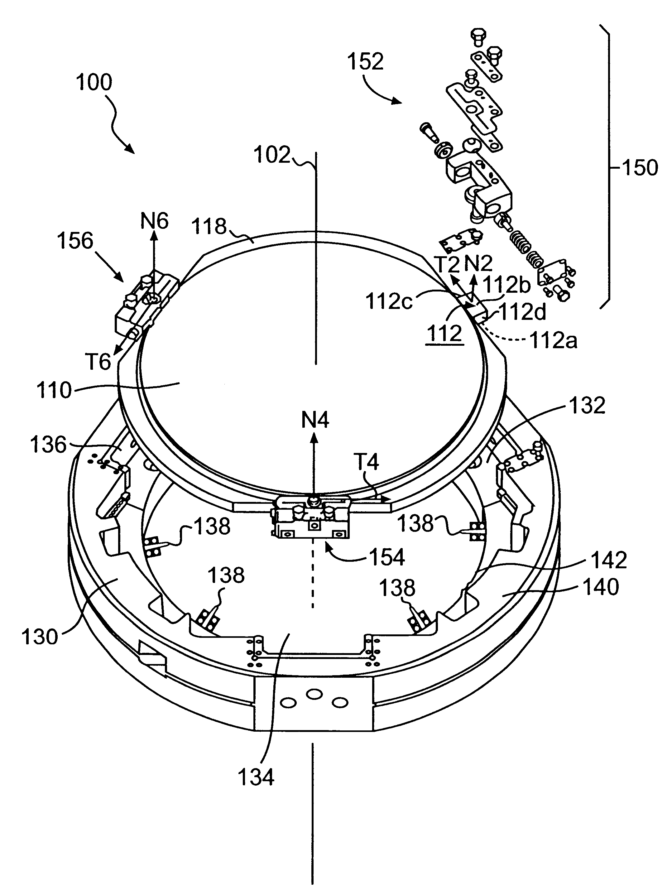
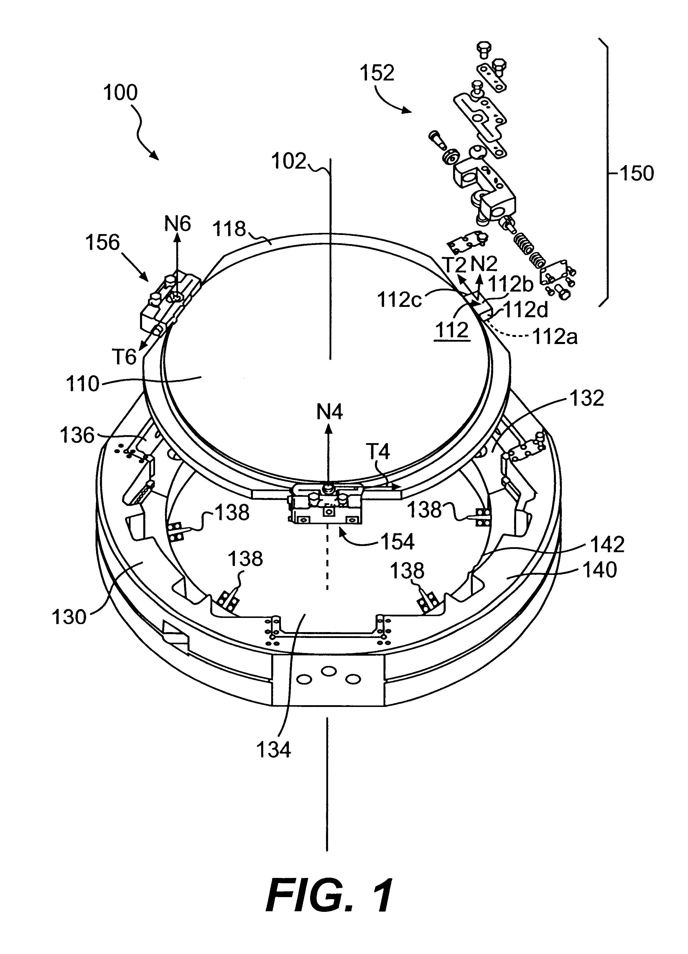
An optical mounting assembly, such as a lens cell assembly, consistent with the principles of this invention is useful to kinematically mount an optical element, such as a lens or a mirror, to an optical holder, such as a lens cell or a mirror frame. One application of this invention is use in a photolithography system to manufacture semiconductor devices. Kinematic mounting in this application means that the lens or mirror is fully supported and precisely constrained by the lens cell or mirror frame in all six degrees of freedom. For practical purposes, the invention will be described with respect to a lens and a lens cell. However, this invention is not limited to that ...


PUM


Abstract

An optical mounting assembly, such as a lens cell assembly, method for making a lens cell assembly, and method for supporting a lens in the lens cell assembly are provided to kinematically mount an optical element to an optical holder. The optical mounting assembly includes an optical element having a plurality of mounting pads distributed around an outer circumference of the optical element, and an optical holder having a corresponding plurality of clamping brackets distributed around an inner circumference of the optical holder. The optical holder supports or constrains movement of the optical element at points of contact between the plurality of mounting pads and the corresponding plurality of clamping brackets both in a normal direction parallel to the optical axis of the assembly and in a tangential direction of the corresponding mounting pad. When the optical element has three mounting pads and the optical holder constrains the optical element at corresponding three clamping brackets, the optical element is constrained in six degrees of freedom, three in the normal direction and another three in the tangential direction at the corresponding mounting pads. The optical mounting assembly of this invention can be used in combination with a projection lens assembly in a semiconductor wafer manufacturing process.

Description

1. Field of the InventionThis invention relates to a kinematic optical mounting to support an optical mounting. More particularly, this invention relates to a kinematic optical mounting to support a lens cell in an optical barrel such as the optical barrel used in the projection lens system for a photolithography process to manufacture semiconductor wafers, or in a photographic camera.2. Description of the Related ArtIn manufacturing integrated circuits using photolithography, light is transmitted through non-opaque portions of a pattern on a reticle, or photomask, through a projection exposure apparatus, and onto a wafer of specially-coated silicon or other semiconductor material. The uncovered portions of the coating, that are exposed to light, are cured. The uncured coating is then removed by an acid bath. Thus, the layer of uncovered silicon is altered to produce one layer of the multi-layered integrated circuit. Conventional systems use visible and ultraviolet light for this pr...

Claims


Application Information

Patent Timeline
IPC IPC(8): G03F7/20G02B7/02H01L21/027
CPCG03F7/70825G02B7/023
Inventor SPINALI, MARC
Owner NIKON CORP
Why Eureka
Try Eureka