Adhesion resistant micromachined structure and coating

a micromachined structure and adhesive technology, applied in the direction of fluid pressure measurement, fluid pressure measurement by electric/magnetic elements, instruments, etc., can solve the problems of direct impact on production yield and reliability of these devices, unwanted adhesion between adjacent elements, and failure of free-standing microstructures to the substrate, so as to prevent and reduce adhesion failure, prevent adhesion failure, and reduce adhesive forces

Inactive Publication Date: 2002-06-11
RGT UNIV OF MICHIGAN
View PDF4 Cites 50 Cited by
  • Summary
  • Abstract
  • Description
  • Claims
  • Application Information

AI Technical Summary

Benefits of technology

Accordingly, an object of the present invention is to provide a technique for preventing and reducing adhesion failure both during the fabrication and operation of micromachined structures.
In addressing this need, the present invention discloses a process that either incorporates a coating for micromechanical structures including amor...

Problems solved by technology

The large surface area to volume ratios of these microstructures, whether processed by surface micromachining, bulk micromachining, wafer dissolving and bonding process, or LIGA process, however, result in problems associated with unwanted adhesion between adjacent elements.
Such adhesive failures have a direct impact on production yield and reliability of these devices.
The sticking of freely standing microstructures to the substrate is a principal source of failures in surface micromachined devices.
Even after ...

Method used


Image

  • Adhesion resistant micromachined structure and coating
  • Adhesion resistant micromachined structure and coating
  • Adhesion resistant micromachined structure and coating

Examples


example 1

Application of AHC as a Protective Coating on Micromachined Structures

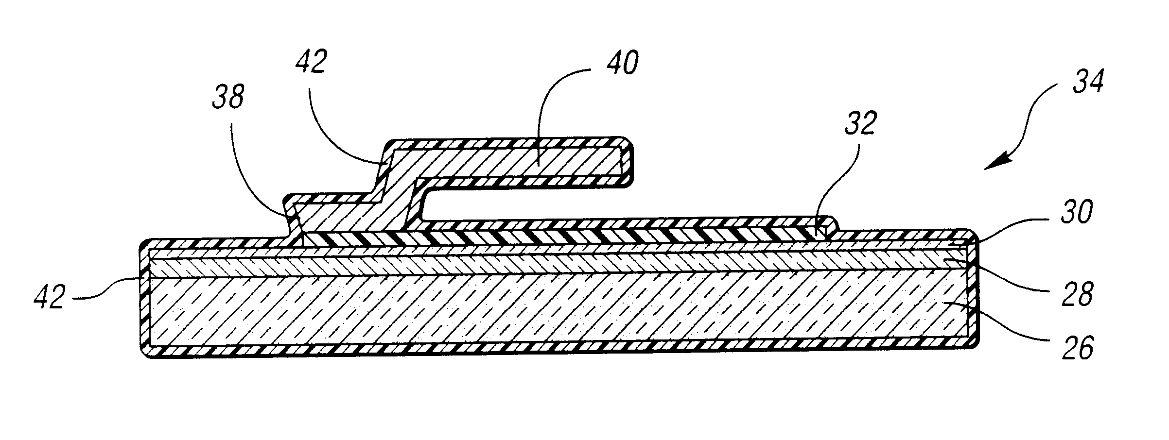
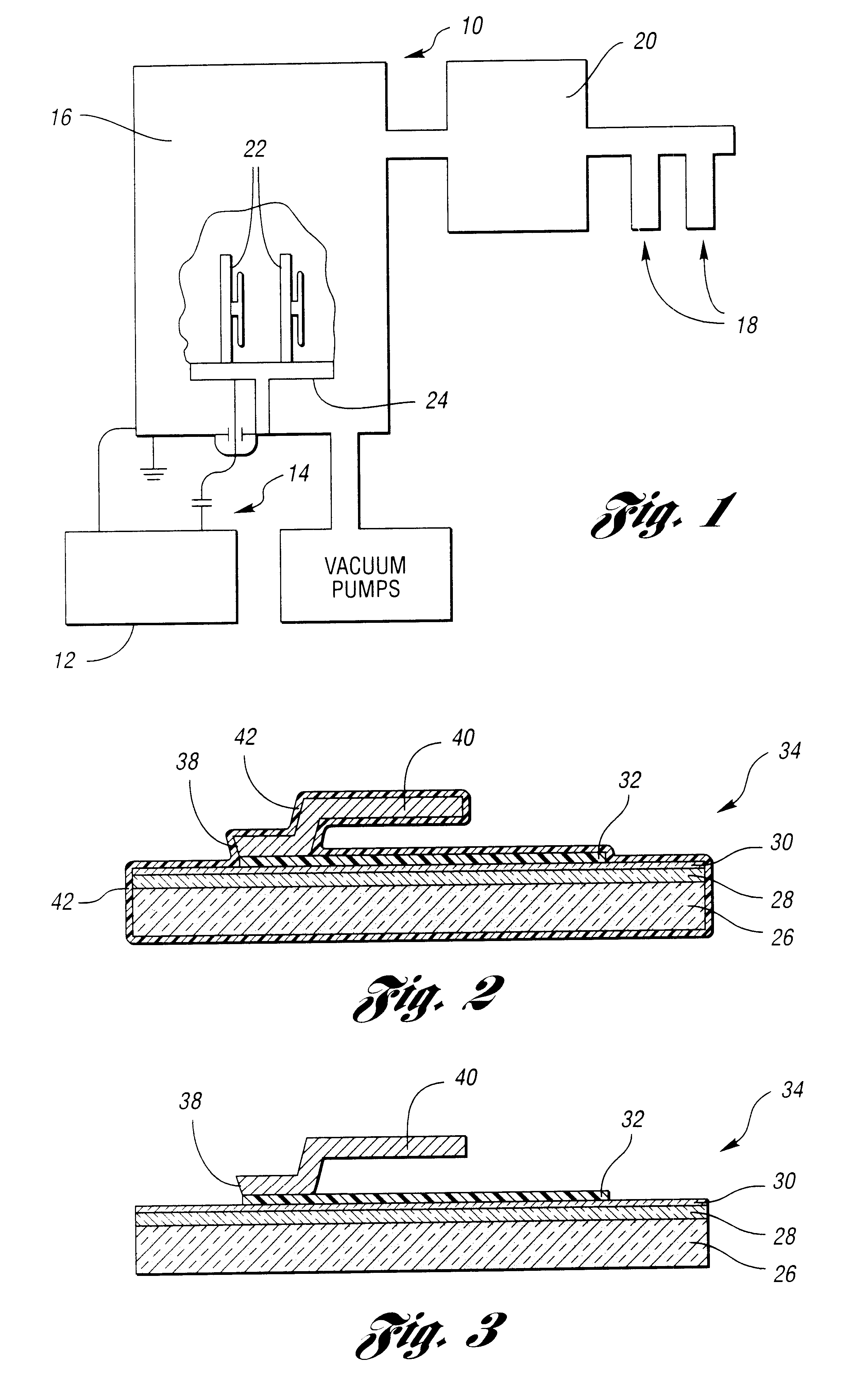
In this example, AHC is used to coat a surface micromachined device 34, as depicted in FIG. 2, consisting of a substrate 26, a patterned polysilicon layer or bottom electrode 32, and a movable micromachined cantilever structure 40.

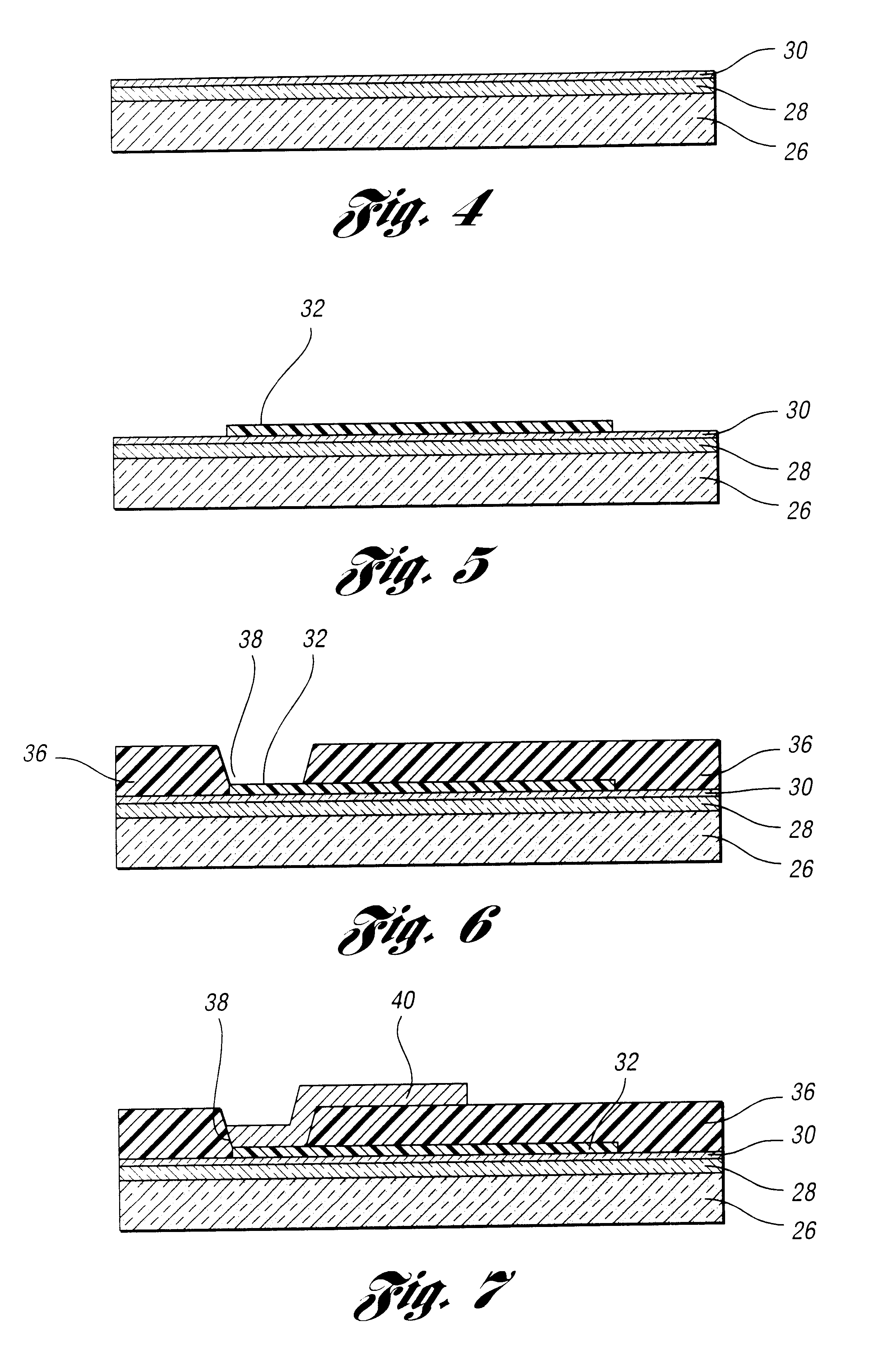
As illustrated in FIG. 4, a silicon wafer 26 is coated with an optional thermal silicon dioxide layer 28, which serves as a passivating layer, preferably having a thickness of 5000 Angstroms. While the substrate in this example is silicon, numerous other substrates function effectively. Possible substrates include, but are not limited to, quartz, glass, aluminum oxide and other such materials. A silicon nitride coating 30 is then applied to serve as a passivating layer onto the silicon substrate 26 or the silicon substrate 26 with a silicon dioxide layer 28. The silicon nitride layer 30 preferably has a thickness in the range of 500 Angstroms to 1500 Angstroms.

In the preferred embodiment...

example 2

Application of AHC as a Micromachined Structure

In this example, application of AHC is incorporated in a surface micromachining process to form a movable cantilever that is made of AHC.

The first three steps of this process consist of preparing a substrate 26, such as a silicon wafer with a silicon dioxide coating 28 and a silicon nitride coating 30, to provide two passivated coatings, depositing a patterned polysilicon layer 32, and depositing and patterning a sacrificial layer 36 made of PSG, which is described in detail in the section above and as shown in FIGS. 4-6.

As further depicted in FIG. 9, a release layer 44, such as a photoresist layer, is then spun on to the micromachined device 34, preferably having a thickness between one micrometer and six micrometers, followed by a photolithography step that defines the overlaying AHC coating. The release layer, most preferably a photolithography patterned photoresist layer, facilitates patterning of the AHC layer. With this preferred ...


PUM

PropertyMeasurementUnit
Electrical resistanceaaaaaaaaaa
Adhesion strengthaaaaaaaaaa

Abstract

A method for fabricating an adhesion-resistant microelectromechanical device is disclosed wherein amorphous hydrogenated carbon is used as a coating or structural material to prevent adhesive failures during the formation and operation of a microelectromechanical device.

Description

TECHNICAL FIELDThis invention is related to the use of amorphous hydrogenated carbon as a micromachined structure or as a coating on micromachined structures which prevents adhesion failures.BACKGROUND ARTMicromachined structures have become increasingly important for a variety of applications. Movable mechanical elements such as cantilevers, beams, and diaphragms are often micromachined for sensors and actuators. Surface micromachining is a microfabrication technology that has attracted great attention, partly because it can produce micromachined structures that can be integrated with electronic devices. With this technology, a sacrificial layer, such as silicon oxide, is first deposited and patterned on a substrate, usually a silicon wafer already coated with silicon nitride. The film for the microstructure is then deposited and patterned. The sacrificial layer is then etched away to release the microstructure, leaving it freely suspended and anchored only where it directly contac...

Claims


Application Information

Patent Timeline
IPC IPC(8): B81B3/00C23C16/26C23C16/30
CPCB81B3/0005B81C1/0096C23C16/30C23C16/26B81C2201/112Y10T156/108Y10T156/11
Inventor HETRICK, ROBERT E.ZHANG, XIA
Owner RGT UNIV OF MICHIGAN
Why Eureka
Try Eureka