Perforated sheet floorplate element

a technology of floorplate elements and perforated sheets, which is applied in the direction of superstructure subunits, superstructures of loading-carrying vehicles, building components, etc., can solve the problems of difficult and excessive manufacturing costs, structures undergo premature ageing, etc., and achieve the effect of easy painting, inspection and cleaning, and considerable eas

Inactive Publication Date: 2002-06-25
LOHR IND
View PDF6 Cites 19 Cited by
  • Summary
  • Abstract
  • Description
  • Claims
  • Application Information

AI Technical Summary

Benefits of technology

it is economical and conformed to industrial mass production;
its shapes make it very easy to paint and to apply a protective layer;
inspection and cleaning prove considerably easier since its volumes are visible and open;
the grooves form cavities which may aid storage or the construction of a floor by engaging therein beams of small section;
it is possible to protect the surface of the floorplate by any suitable treatment before mounting it on its support;

Problems solved by technology

These mechanical stresses entail the multiplication of weld seams necessary in places frequently of difficult access.
These structural requirements entail difficulties and excessive manufacturing costs.
Moreover, the crossbeams used consist of shaped members of partially or totally closed section defining cavities accessible only with difficulty to anti-rust protection products, paint and maintenance and cleaning products, even if the later are atomized under pressure.
Through a lack of protection and maintenance, these structures undergo premature ageing caused mainly by bad weather and the difficulty of providing effective protection.

Method used


Image

  • Perforated sheet floorplate element
  • Perforated sheet floorplate element
  • Perforated sheet floorplate element

Examples


Embodiment Construction

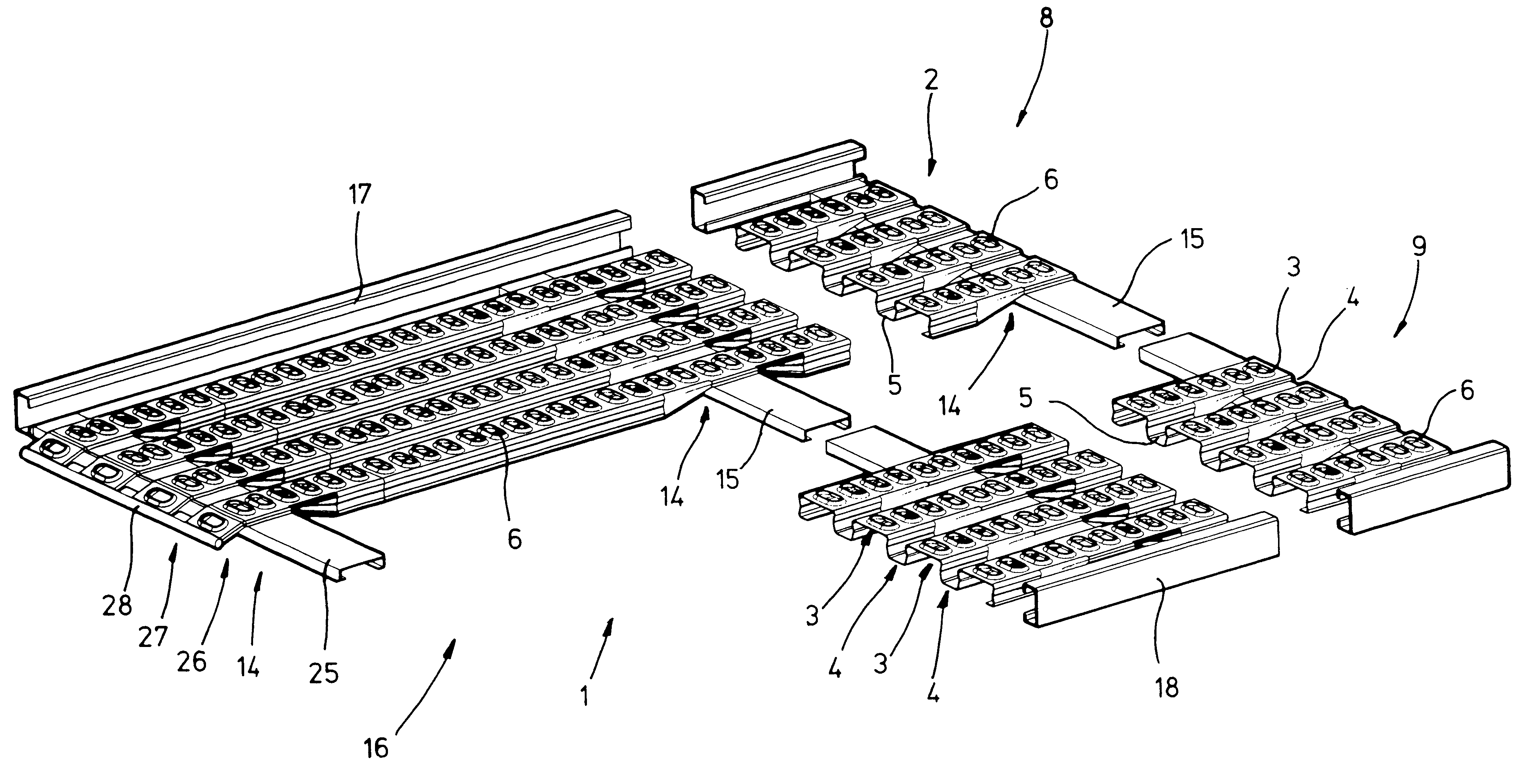
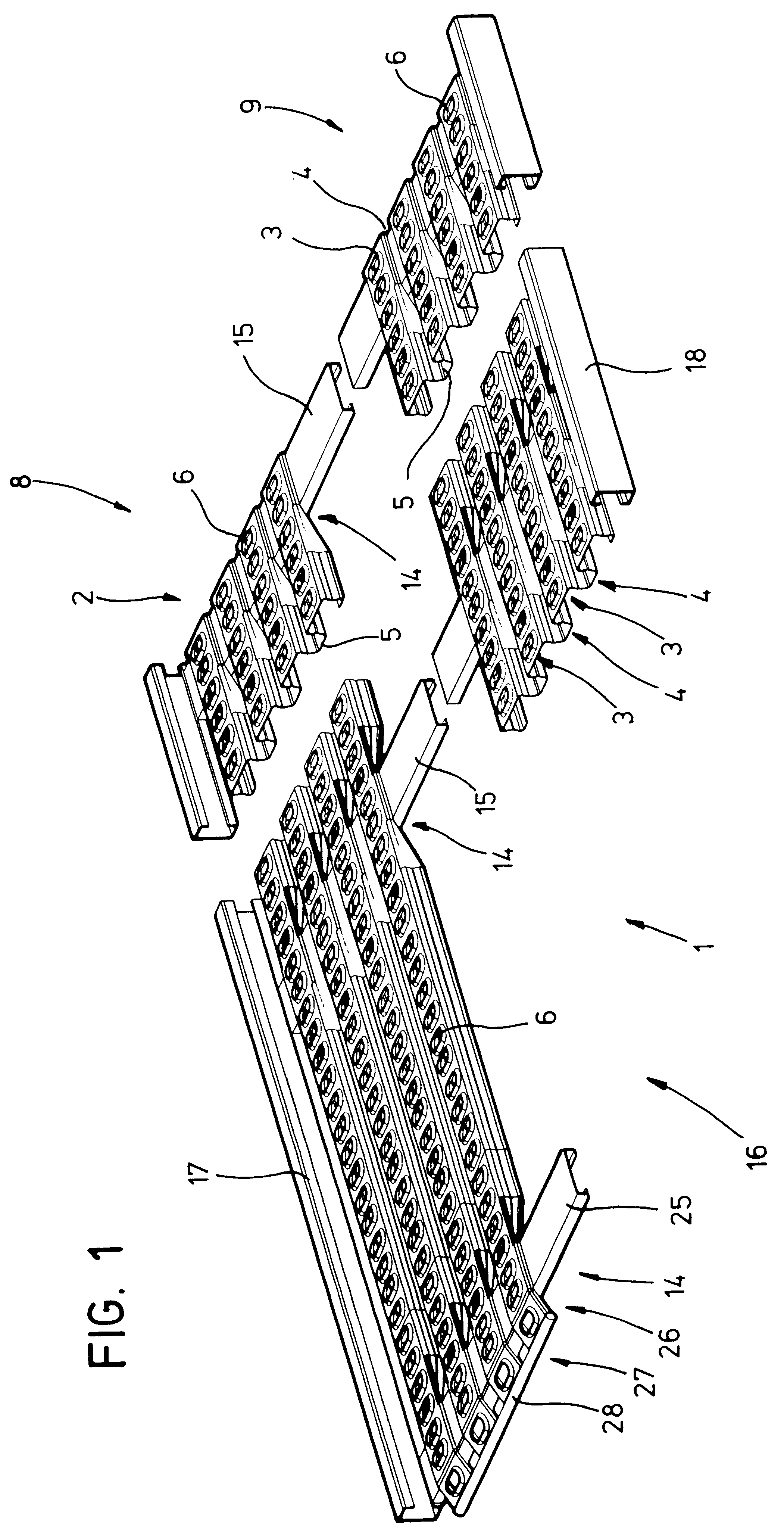
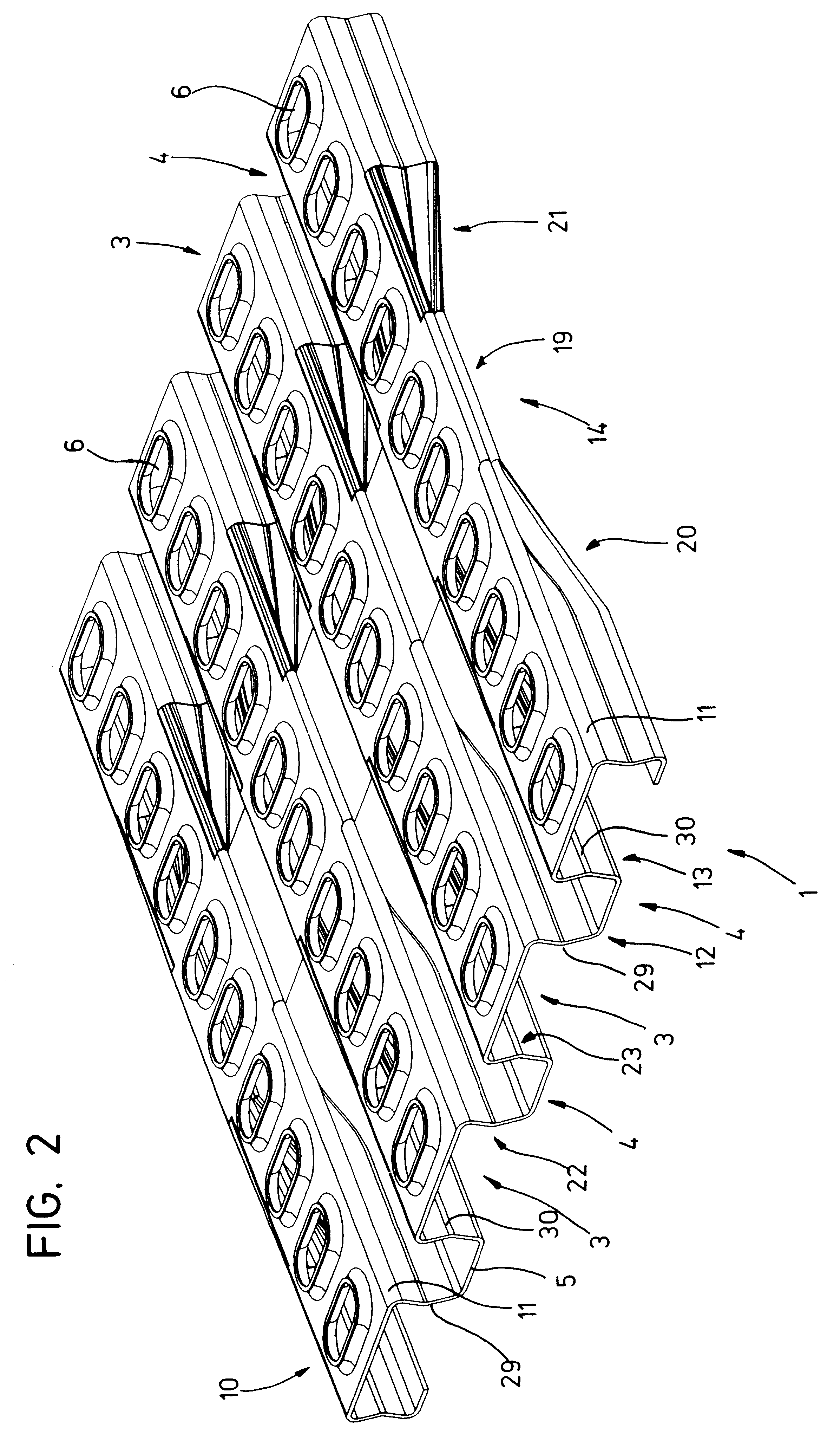
The current floorplate element 1 forming the subject matter of the present invention is formed from a sheet format previously folded into transverse corrugations 2 in the form of a sequence of crenellations alternately exhibiting a, preferably planar, raised area 3, and a longitudinal groove 4 with, for example, a flat bottom 5.

The format sheet is then perforated by embossing or cutting along longitudinal lines of perforations 6 along the median part of each raised area 3.

The edges such as 7 of the perforations 6 are either raised to form an anti-skid surface in the case of a vehicle-transporting body or oriented downwards, that is to say inwardly, in the case of a smooth surface required for freight transport.

This corrugated formation with planar raised areas 3 and grooves 4 with flat bottoms ensures adequate rigidification of the structure for the application envisaged.

The raised areas 3 comprising perforations constitute as many elementary running surfaces separated by the longit...


PUM

PropertyMeasurementUnit
compression forcesaaaaaaaaaa
heightaaaaaaaaaa
areasaaaaaaaaaa

Abstract

A floorplate element formed from a perforated sheet metal in which the floorplate element has a sequence of raised areas and recessed grooves. The floorplate element has at least one thinner transverse recessed area which results from a compression-pinching of the perforated sheet metal of a bottom surface of the grooves towards an top surface of the raised areas. Each transverse recessed area forms a surface for supporting the floorplate element on a crossbeam of a supporting structure. The invention is suitable for use in commercial vehicles as a loading surface.

Description

The present invention relates to a floorplate element for use as a bearing surface for a deck or platform of a commercial vehicle.One of the applications envisaged relates to car-transporter vehicles.This element is manufactured in large format with a view to being able to cut it to the precise dimensions of the frame structures which carry the floorplate.PRIOR ARTAt present, to cover the supporting framework of a vehicle loading deck, there are used perforated sheet plates resting on the rigidifying structure of a base frame.This base frame comprises crossbeams firmly connected with longitudinal beams on which are mounted the perforated sheet plates.Since the vehicle-transporting decks thus formed are mechanically stressed during transportation, it is advisable to immobilize sufficiently the supporting structures and their covering plates.Thus, both the elements of the rigidifying structures of the supporting surface and the perforated plates are welded at numerous points.These mec...

Claims


Application Information

Patent Timeline
Patent Type & Authority Patents(United States)
IPC IPC(8): B62D33/02B62D25/20E01D19/12E04C2/32
CPCB62D25/2054B62D33/02E04C2/322E01D19/125Y10T29/49622E01D2101/30
Inventor DECKERT, SERGE
Owner LOHR IND
Why Eureka
Try Eureka