Resilient containers for hyperpolarized gases and associated methods

a technology of hyperpolarized gas and containers, applied in the direction of liquid dispensing, non-pressured vessels, dispensing, etc., can solve the problems of hyperpolarized gas deterioration or decay, less than satisfactory images, and relatively rapid decay from the polarized state, so as to reduce the exposure to potentially depolarizing materials, reduce stress/strain, and reduce the effect of stress or strain

Inactive Publication Date: 2002-07-23
HESKA +1
View PDF29 Cites 35 Cited by
  • Summary
  • Abstract
  • Description
  • Claims
  • Application Information

AI Technical Summary

Benefits of technology

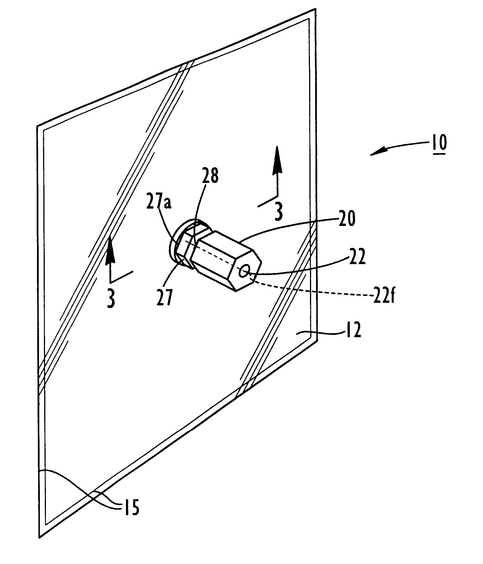
As is also shown in FIG. 9, the capillary stem 26s is positioned intermediate the valve member 26 and the container chamber 14 to inhibit the migration of the hyperpolarized substance into the valve member 26 to reduce the exposure to any potentially depolarizing materials therein (which potentially includes one or more of the O-rings 26o). Preferably, all sealing and structural materials associated with the container 10 and other container assembly components which come into contact with hyperpolarized gas are selected or formed of materials which are preferably substantially non-depolarizing.
Preferably, the capillary stem 26s is formed with a substantially rigid body. As used herein, the term "rigid" means that it can structurally help support the weight of a valve member 26 when assembled to the container 10 to minimize the stress/strain which may be introduced onto th

Problems solved by technology

However, it has recently been discovered that polarized noble gases can produce improved images of certain areas and regions of the body which have heretofore produced less than satisfactory images in this modality.
Unfortunately, as will be discussed further below, the polarized state of the gases are sensitive to handling and environmental conditions and, undesirably, can decay from the polarized state relatively quickly.
Unfortunately, during and after collection, the hyperpolarized gas can deteriorate or decay (lose its hyperpolarized state) relatively qui

Method used


Image

  • Resilient containers for hyperpolarized gases and associated methods
  • Resilient containers for hyperpolarized gases and associated methods
  • Resilient containers for hyperpolarized gases and associated methods

Examples


example 1

.sup.3 He LDPE / HDPE Bag

An exemplary one liter patient delivery bag, such as is shown in FIG. 7, is a 7 inch.times.7 inch square. The expected T.sub.1 for .sup.3 He can be determined using (Equation 2.4) and the theoretical relaxivity of LDPE for .sup.3 He quoted in Table 4.3. The associated area (A=2*18 cm* 18 cm) is 648 cm.sup.2, the volume is 1000 cubic centimeters, and the relaxivity is 0.0012 cm / min. Equation 2.4 leads to a T.sub.1 of about 1286 min or 21.4 hours for an LDPE bag configured and sized as noted above (absent other relaxation mechanisms). For a bag made of HDPE, which has a lower relaxivity value of about 0.0008 cm / min (attributed to the lower .sup.3 He solubility), the T.sub.1 is estimated at 32 hours. In deuterated HDPE, the T.sub.1 is expected to be about 132 hours.

example 2

.sup.129 Xe LDPE / Nylon Bag

The same 1 liter LDPE patient delivery bag as described in Example 1 contains hyperpolarized .sup.129 Xe. Volume and surface area are the same but the theoretical relaxivity is 0.0419 cm / min (Table 4.2) for .sup.129 Xe on LDPE. The relaxivity is much higher because of the higher solubility of .sup.129 Xe in LDPE compared to He (S.sub.Xc =0.68 vs S.sub.He =0.006). For this configuration, T.sub.1 is estimated at 36.8 minutes. Similarly, for the measured relaxivity for Nylon-6 of 0.0104 cm / min, predict T.sub.1 is predicted to be about 148 min or about 2.4 hours. This value is close to what has been measured for the presently used Tedlar.TM. bags.

example 3

Metal Film Surface

In this example, metal film coatings are used as the contact surface. The 7".times.7" square bag described in Example 1 is employed but coated or formed with high purity aluminum on its internal contact surface (the surface in contact with the hyperpolarized gas). The relaxivity of high purity aluminum for .sup.129 Xe has been recently measured to be about 0.00225 cm / min. (One readily available material suitable for use is Reynold's.TM. heavy duty freezer foil). Doing the calculation, one can obtain a container with an extended T.sub.1 for xenon of about 11.43 hours. This is a great improvement in T.sub.1 for Xe. Similarly, the use of such metal film surfaces for 3He can generate T.sub.1 's in the range of thousands of hours (the container no longer being a limiting factor as these T.sub.1 's are above the theoretical collisional relaxation time described above). Metals other than aluminum which can be used include indium, gold, zinc, tin, copper, bismuth, silver, ...


PUM

PropertyMeasurementUnit
Lengthaaaaaaaaaa
Fractionaaaaaaaaaa
Timeaaaaaaaaaa

Abstract

A resilient multi-layer container is configured to receive a quantity of hyperpolarized noble fluid such as gas and includes a wall with at least two layers, a first layer with a surface which minimizes contact-induced spin-relaxation and a first or second layer which is substantially impermeable to oxygen. The container is especially suitable for collecting and transporting 3He. The resilient container can be formed of material layers which are concurrently responsive to pressure such as polymers, deuterated polymers, or metallic films. The container can include a capillary stem and/or a port or valve isolation means to inhibit the flow of gas from the main volume of the container during transport. The resilient container can be configured to directly deliver the hyperpolarized noble gas to a target interface by deflating or collapsing the inflated resilient container. In addition, single layer resilient containers with T1's of above 4 hours for 129Xe and above 6 hours for 3He include materials with selected relaxivity values. In addition, a bag with a port fitting or valve member and one or more of a capillary stem and port isolation means is configured to minimize the depolarizing effect of the container valve or fitting(s). Also disclosed is a method for determining the gas solubility in an unknown polymer or liquid using the measured relaxation time of a hyperpolarized gas.

Description

The present invention relates to processing, storage, transport and delivery containers for hyperpolarized noble gases.Conventionally, Magnetic Resonance Imaging ("MRI") has been used to produce images by exciting the nuclei of hydrogen molecules (present in water protons) in the human body. However, it has recently been discovered that polarized noble gases can produce improved images of certain areas and regions of the body which have heretofore produced less than satisfactory images in this modality. Polarized Helium-3 (".sup.3 He") and Xenon-129 (".sup.129 Xe") have been found to be particularly suited for this purpose. Unfortunately, as will be discussed further below, the polarized state of the gases are sensitive to handling and environmental conditions and, undesirably, can decay from the polarized state relatively quickly.Hyperpolarizers are used to produce and accumulate polarized noble gases. Hyperpolarizers artificially enhance the polarization of certain noble gas nucle...

Claims


Application Information

Patent Timeline
IPC IPC(8): A61K49/18A61K49/06F17C13/00F17C1/00F17C3/00G01R33/28
CPCA61K49/1815F17C3/00F17C13/002F17C13/005G01R33/282F17C1/00Y10T428/1379F17C2201/018F17C2201/058F17C2203/0607F17C2203/0619F17C2203/0621F17C2203/0624F17C2203/0646F17C2203/066F17C2205/0323F17C2205/0382F17C2205/0394F17C2221/014F17C2221/017F17C2221/07F17C2223/0123F17C2223/0153F17C2223/033F17C2225/0123F17C2225/033F17C2227/0142F17C2227/044F17C2250/0473F17C2260/03F17C2270/02F17C2270/079Y10S62/919Y10T428/1334Y10T428/1352
Inventor ZOLLINGER, DAVID L.DEATON, DANIEL M.DRIEHUYS, BASTIAANHASSON, KENTON C.
Owner HESKA
Why Eureka
Try Eureka