

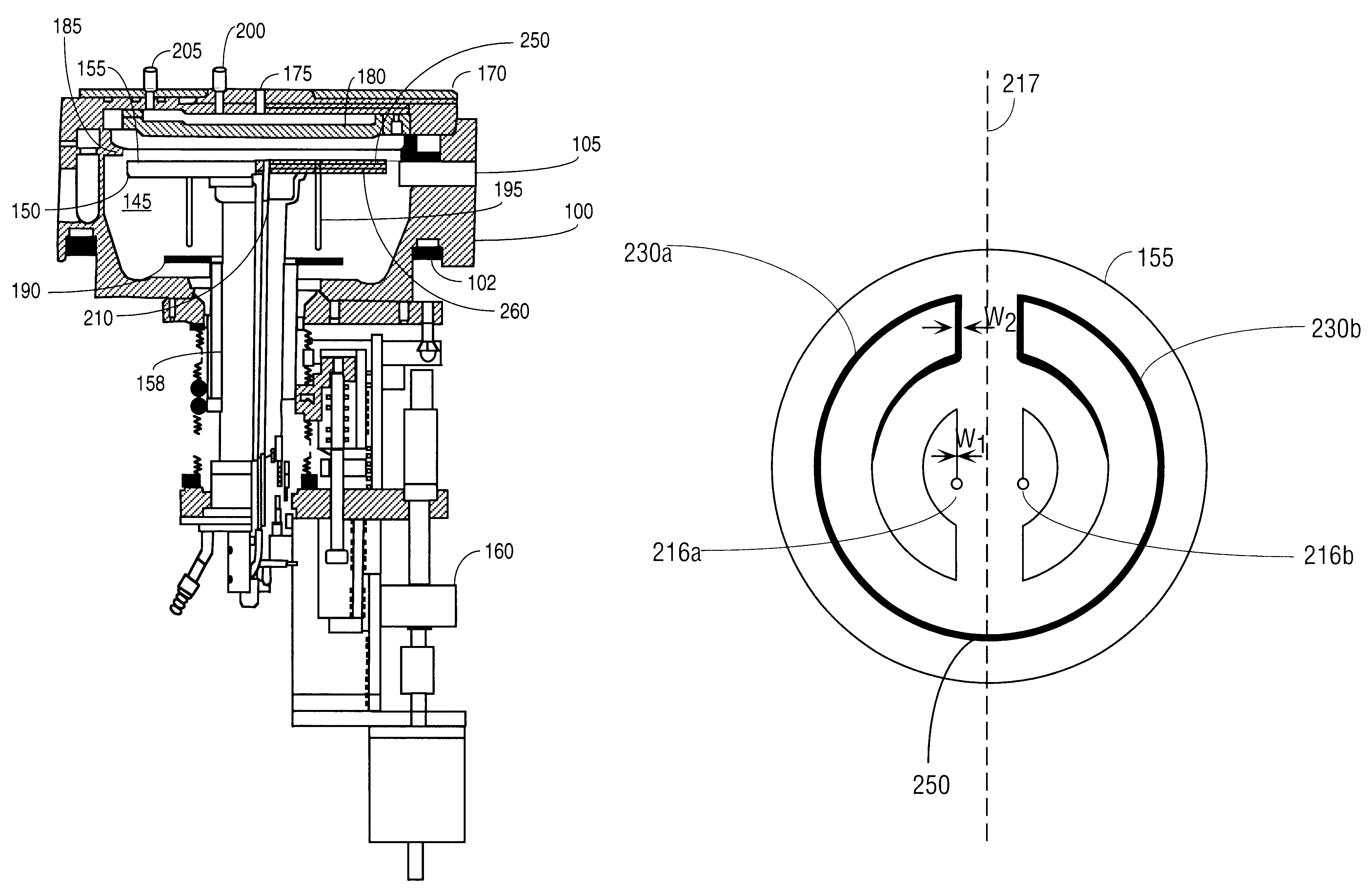
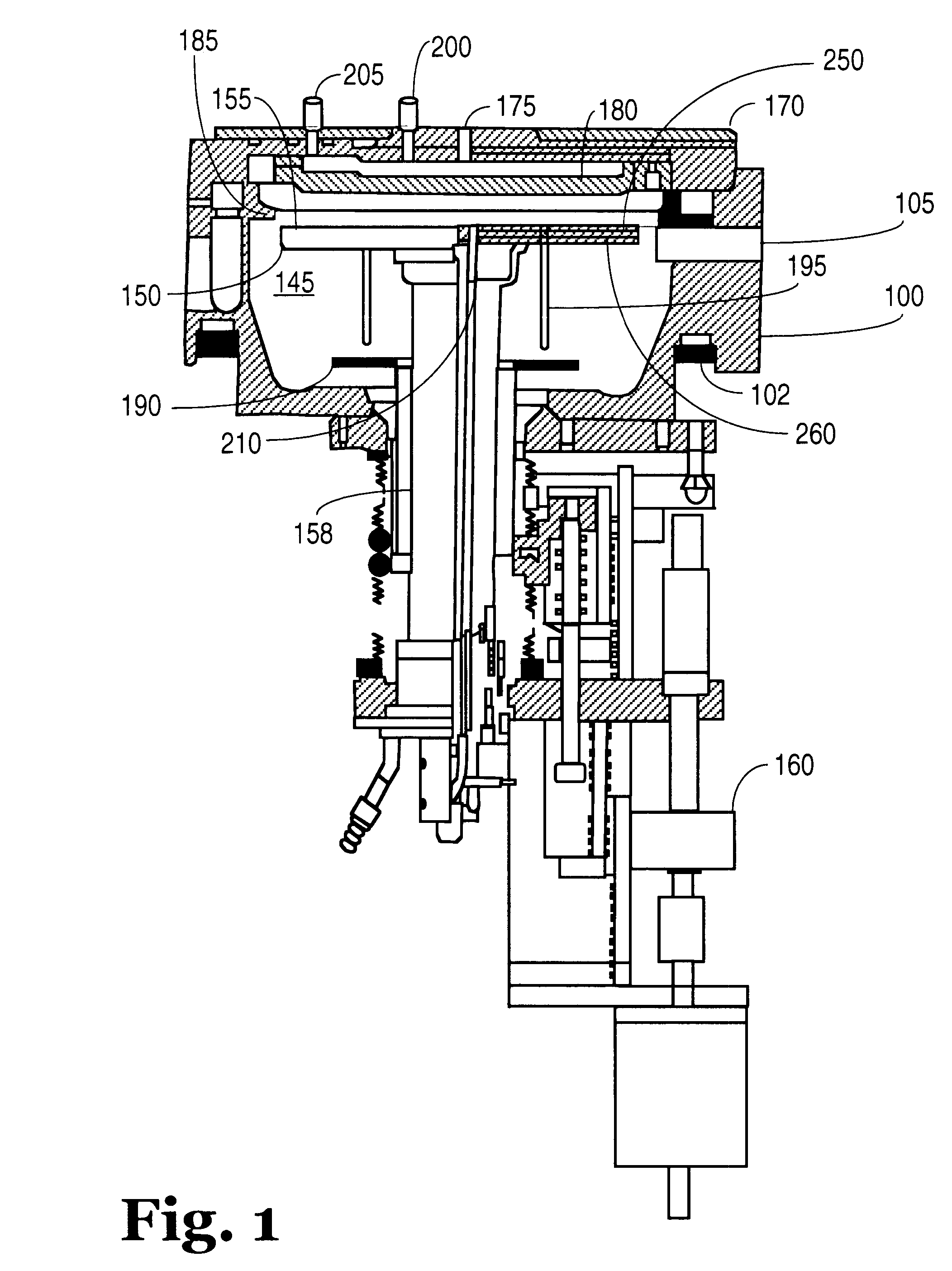
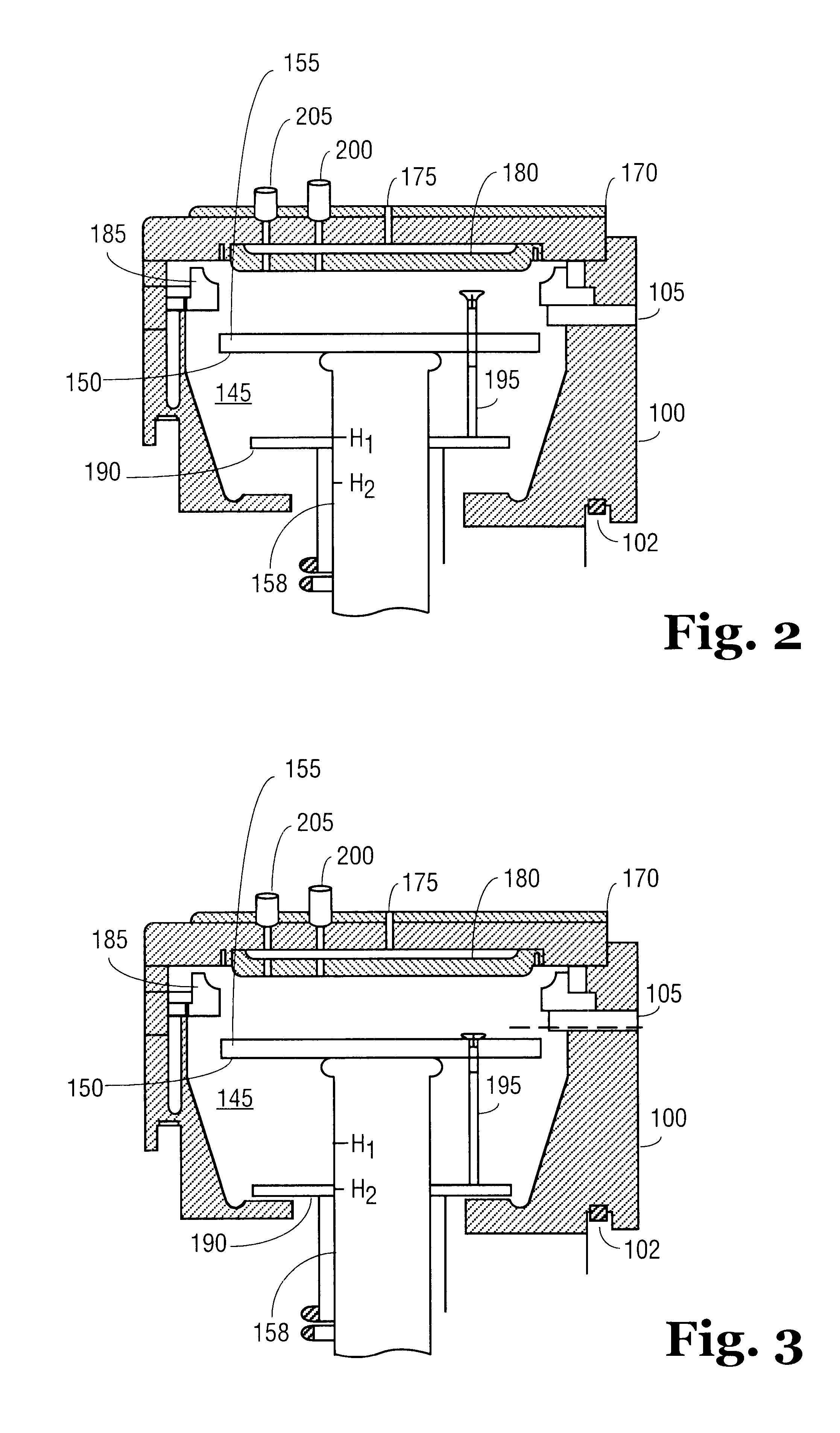
Multi-zone resistive heater
a resistive heater and multi-zone technology, applied in the direction of ohmic resistance heating, hot plate heating arrangement, coating, etc., can solve the problems of difficult control of the temperature in the chamber, difficulty in uniform temperature, and single-zone resistive heaters that typically do not have the ability to compensate for differences
- Summary
- Abstract
- Description
- Claims
- Application Information
AI Technical Summary
Benefits of technology
Problems solved by technology
Method used
Image

Examples
Embodiment Construction
(Inner) Heater PID Voltage=(49.1%+3.4%+3.0%+0%)-2.0%=53.5%=>107VAC
Feedforward leg=750*(0.655 / (2000+2000*2 2)=>49.1%* P leg=0.8*(142.7*30 / (2000+2000*2 2)=>3.4%
(Outer) Heater Voltage=1.15*107=>123VAC Power Ratio=1.5
*Note: Arrows in calculations indicate that the calculated value shown is different in magnitude by a factor of 10.sup..times..
For PIDF control, the voltage ratio depends on the heater temperature range.
A. If Setting temperature (.degree. C.) is below [TL]:
Voltage Ratio=[R.sub.L ]
Note: R.sub.L =Voltage Ratio of Low Temperature Ramp
T.sub.L =Temperature Limit of Low Ramp (.degree. C.)
B. If Setting Temperature (.degree. C.) is between [T.sub.L ] and [T.sub.H ]
Voltage Ratio=[R.sub.L ]+([R.sub.H ]-[R.sub.L ])*(Setting temperature-[T.sub.L ]) / ([T.sub.H ]-[T.sub.L ])
Note: R.sub.L =Voltage Ratio of Low Temperature Ramp
R.sub.H =Voltage Ratio of High Temperature Ramp
T.sub.H =Temperature Limit of High Ramp (.degree. C.)
T.sub.L =Temperature Limit of Low Ramp (.degree. C.)
C. Voltage Rat...
PUM
| Property | Measurement | Unit |
|---|---|---|
| angle | aaaaa | aaaaa |
| angle | aaaaa | aaaaa |
| temperatures | aaaaa | aaaaa |
Abstract
Description
Claims
Application Information