Radiating source for a transmit and receive antenna intended to be installed on board a satellite

a technology for transmitting and receiving antennas, applied in the field of transmitting and receiving systems, can solve the problems of reducing the overall lack of symmetry about the axis of the reflector, preventing correct isolation, and unsuitable high-efficiency smooth conical horn radiating apertures, so as to maximize radiation symmetry and improve the symmetry of radiation pattern

Inactive Publication Date: 2002-07-23
ALCATEL LUCENT SAS
View PDF8 Cites 6 Cited by
  • Summary
  • Abstract
  • Description
  • Claims
  • Application Information

AI Technical Summary

Benefits of technology

The invention aims to provide a transmit and receive system in which each wide-band primary source is free of the disadvantages of the prior art solutions, i.e. achieves a sufficiently low level of illumination at the periphery of the transmit reflector.
Other things being equal, and in particular the area of the reflector, for example that of a circle with a diameter of approximately 50 mm, compared to a corrugated radiating aperture, each radiating aperture, which has an efficiency of at least 70%, is more directional, which reduces the energy at the edge of the reflector. A corrugated radiating aperture has an efficiency (gain) of at most 60%.
It should be noted that, until now, it has been considered that a high-efficiency smooth conical horn radiating aperture is not suitable for this type of wide-band source because it cannot produce a circularly symmetrical radiation pattern and the radiation pattern has large secondary lobes, preventing correct isolation between zones to which the same frequency sub-bands are allocated. However, the invention overcomes at least the major part of this drawback, because the radiating sources are not very directional, compared to the source consisting of the set of apertures, and the distribution of the radiation from each high-efficiency radiating aperture reduces the overall lack of symmetry about the axis of the reflector, because it reduces the difference between the radiating levels in two planes perpendicular to each other and to the reflector.
To improve the symmetry of the radiation pattern about the axis of the reflector, or about the axis of the set of radiating apertures, according to one feature of the invention, the various radiating apertures are fed with linear polarization and the polarization is oriented relative to the disposition of the various radiating apertures to maximize the symmetry of the radiation about the axis of the radiating source. For example, if the radiating apertures are distributed so that there is a direction passing through the center of the radiating source through which a maximum number of centers of radiating apertures passes, the polarization direction perpendicular to that direction is chosen.
To prevent the lobes of the array of radiating apertures constituting the radiating source reducing the power to be transmitted in the wanted direction, the distance between the centers of the radiating apertures is less than one wavelength at the transmit frequency (the lower frequency). For example, when the transmit frequency is 20 GHz, the distance between the radiating apertures must be less than approximately 16 mm.
In an embodiment, the radiation to be transmitted by the source has linear polarization in a particular direction and the feed means are such that each radiating aperture transmits radiation polarized in said particular direction which is oriented relative to the set of radiating apertures in such a manner as to maximize the uniformity of the radiation in three dimensions.

Problems solved by technology

It should be noted that, until now, it has been considered that a high-efficiency smooth conical horn radiating aperture is not suitable for this type of wide-band source because it cannot produce a circularly symmetrical radiation pattern and the radiation pattern has large secondary lobes, preventing correct isolation between zones to which the same frequency sub-bands are allocated.
However, the invention overcomes at least the major part of this drawback, because the radiating sources are not very directional, compared to the source consisting of the set of apertures, and the distribution of the radiation from each high-efficiency radiating aperture reduces the overall lack of symmetry about the axis of the reflector, because it reduces the difference between the radiating levels in two planes perpendicular to each other and to the reflector.

Method used


Image

  • Radiating source for a transmit and receive antenna intended to be installed on board a satellite
  • Radiating source for a transmit and receive antenna intended to be installed on board a satellite
  • Radiating source for a transmit and receive antenna intended to be installed on board a satellite

Examples


Embodiment Construction

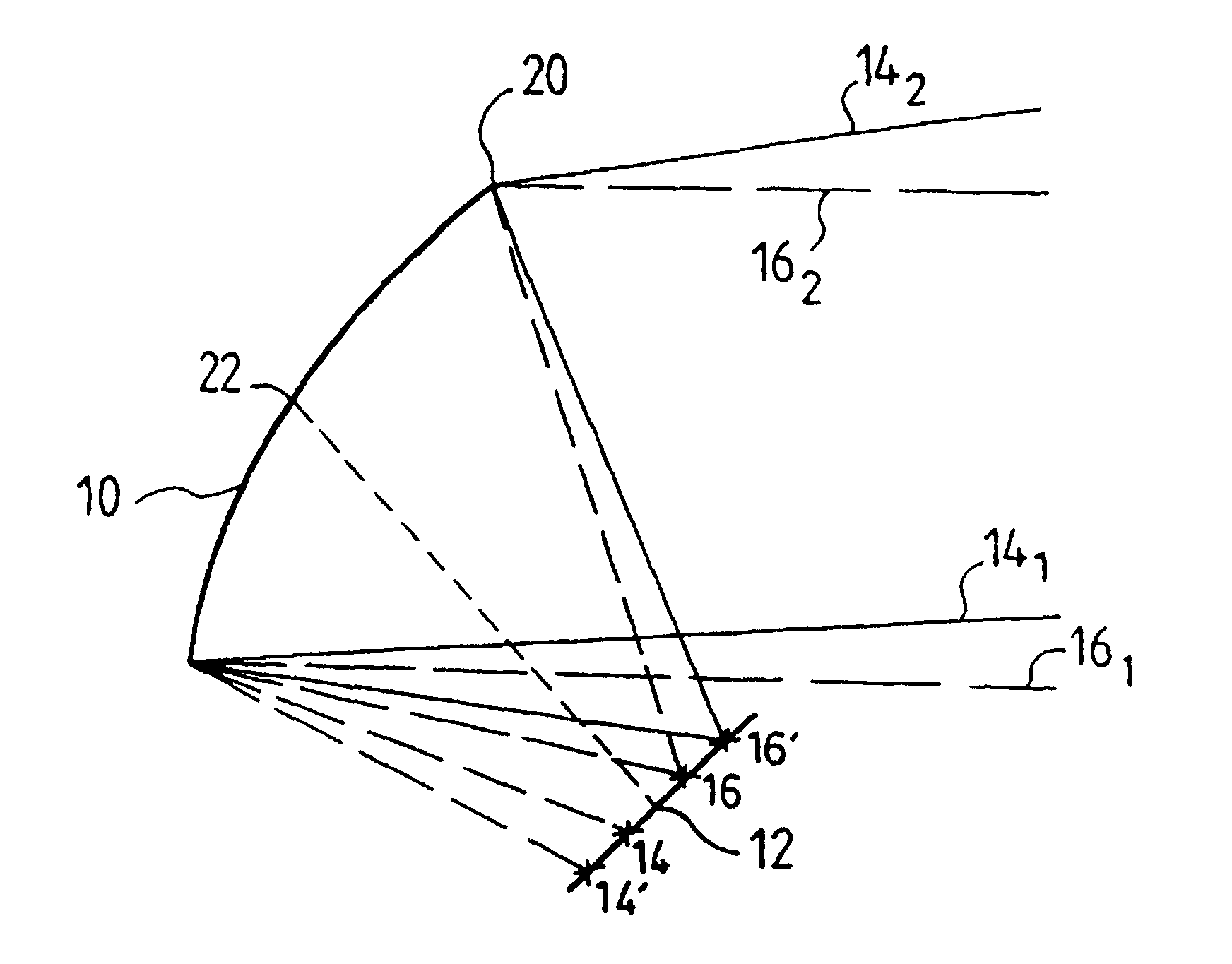
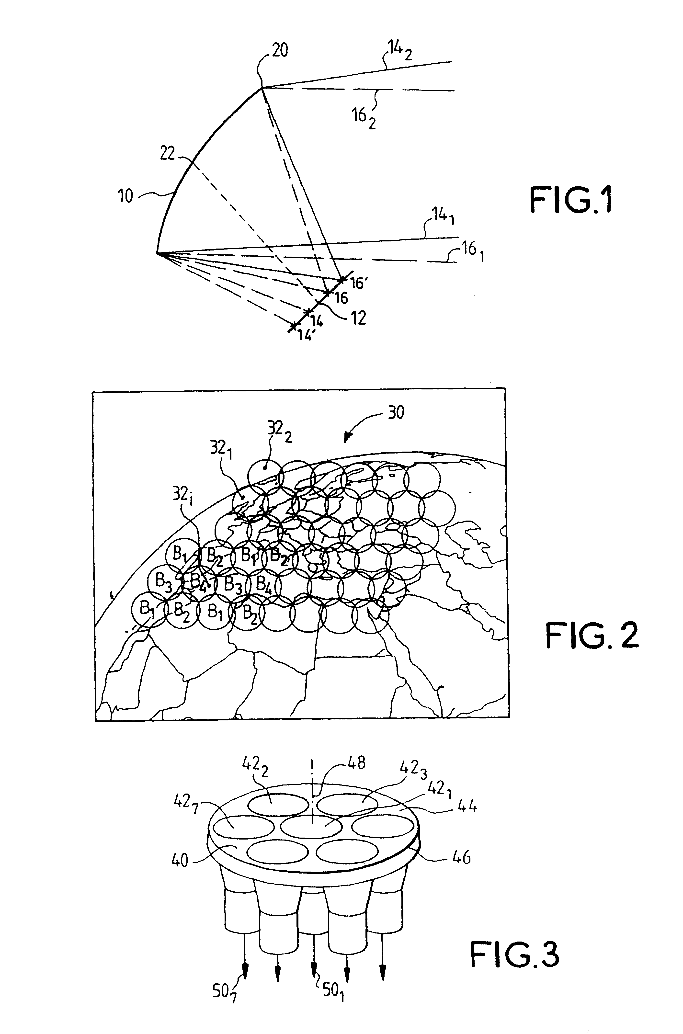
The embodiment of the invention described with reference to the drawings is a transmit and receive radiating source 40 intended to be installed on board a geosynchronous satellite (not shown) constituting a relay for calls of a telecommunications system in a region 30 (FIG. 2) covering a large part of the European continent and part of the African continent. The region is divided into circular zones 32.sub.1, 32.sub.2, etc.

The whole of the region 30 is covered by the geosynchronous satellite (in orbit 36 000 km above the surface of the globe) with a cone of 6.degree. total aperture. The angular distance (as seen from the satellite) between the centers of two adjoining zones is 0.5.degree..

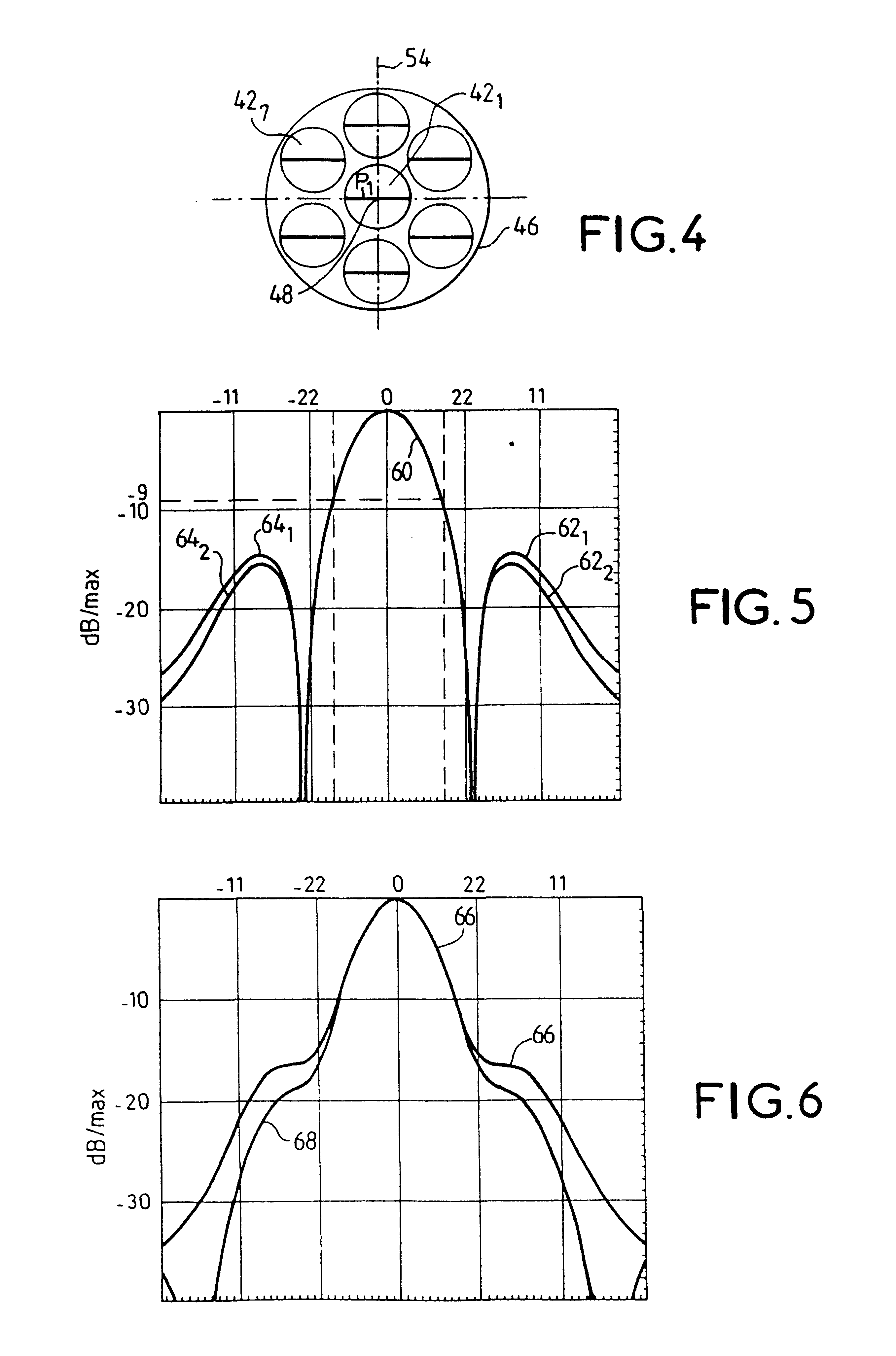
In this example, where the total number of zones 32.sub.i is 48, the satellite includes four reflectors and each reflector is associated with 12 primary sources corresponding to non-adjacent zones.

In the embodiment shown, each transmit and receive band is divided into four sub-bands B1, B2, B3 and ...


PUM


Abstract

The invention relates to a radiating source for transmitting and receiving, intended to be installed on board a satellite to define a radiation pattern in a terrestrial zone, said source being intended to be disposed in or near the focal plane of a reflector associated with other sources corresponding to other terrestrial zones. The source includes a plurality of radiating apertures, each of which has an efficiency at least equal to 70%, and feed means for feeding said radiating apertures. The radiating apertures and their feed means are such that the energy radiated by all of the radiating apertures is practically limited to the corresponding reflector, at least for transmission.

Description

The invention relates to a transmit and receive antenna on board a satellite forming part of a telecommunications system in which said antenna relays calls in a terrestrial region divided into a plurality of zones. The region is divided into zones by allocating to each zone a primary source consisting of individual radiating entities that can be common to a plurality of sources.Compared to global coverage, dividing the region covered by the satellite into zones has the advantage that energy performance is improved and frequencies can be re-used from one zone to another. For example, the allocated frequency band can be divided into a plurality of sub-bands and the sub-bands can be distributed so that two adjacent zones use different sub-bands.A region covered by a satellite is divided into zones both for geosynchronous satellites and for non-geosynchronous satellites. The following description is limited to a geosynchronous satellite telecommunications system, but the invention also ...

Claims


Application Information

Patent Timeline
Patent Type & Authority Patents(United States)
IPC IPC(8): H01Q19/17H01Q19/10H01Q1/28B64G1/66H01Q21/30H01Q25/00H04B7/185
CPCH01Q19/17
Inventor MANGENOT, CYRILCAILLOCE, YANNMAUREL, JACQUES
Owner ALCATEL LUCENT SAS
Why Eureka
Try Eureka