
Plastic housing with condensation protection for electric and electronic assemblies

a technology of plastic housing and electronic components, applied in the direction of electric apparatus casings/cabinets/drawers, hermetically sealed casings, instruments, etc., can solve the problems of high maintenance and repair costs, no longer accessible electric and electronic components, and inability to condense air in the housing

Inactive Publication Date: 2002-09-03
DAIMLER AG
View PDF27 Cites 45 Cited by
  • Summary
  • Abstract
  • Description
  • Claims
  • Application Information

AI Technical Summary

Benefits of technology

In this manner, according to the invention, the dangers of short-circuiting, circuiting, leakage currents, and corrosion can be avoided. Also, the electric and electronic components within the housing remain freely accessible for testing and maintenance purposes, so that any necessary changes can be carried out. Also, for recycling the overall housing-enclosed assembly, it is a simple matter to separate the metal parts and the plastic parts for separately recycling these respective parts. The invention is especially suitable for use in plastic housings enclosing electric and electronic components, such as those typically included in control devices provided in motor vehicles.

Problems solved by technology

While such plastic housings are typically protected against direct entry of water sprays or the like, they are often not hermetically tightly sealed, so that humidity or moisture in the air can penetrate into the interior of such plastic housings.
This leads to the disadvantage, that a reduction in the environmental mental temperature can cause the humidity or moisture in the air within the housing to condense therein.
Such protective measures, however, cause the disadvantage that the electric and electronic components are no longer accessible in order to test the components, update or maintain software, monitor the long-term behavior thereof, or the like.
For this reason, it often becomes necessary to exchange the entire electric or electronic assembly such as a control device, rather than simply exchanging individual components thereof, which thus leads to higher maintenance and repair costs.

Method used


Image

  • Plastic housing with condensation protection for electric and electronic assemblies
  • Plastic housing with condensation protection for electric and electronic assemblies

Examples


Embodiment Construction

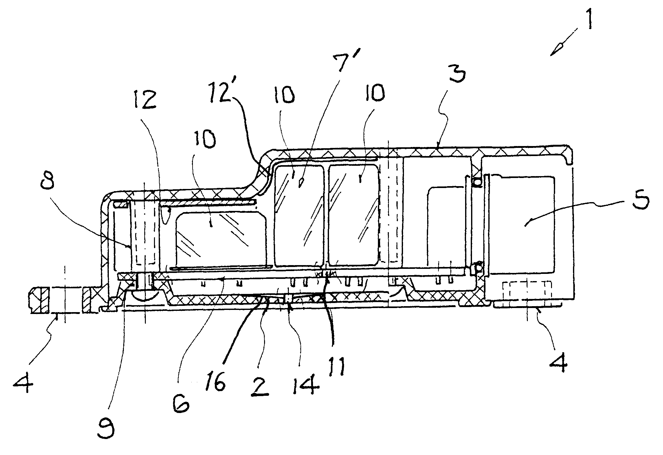
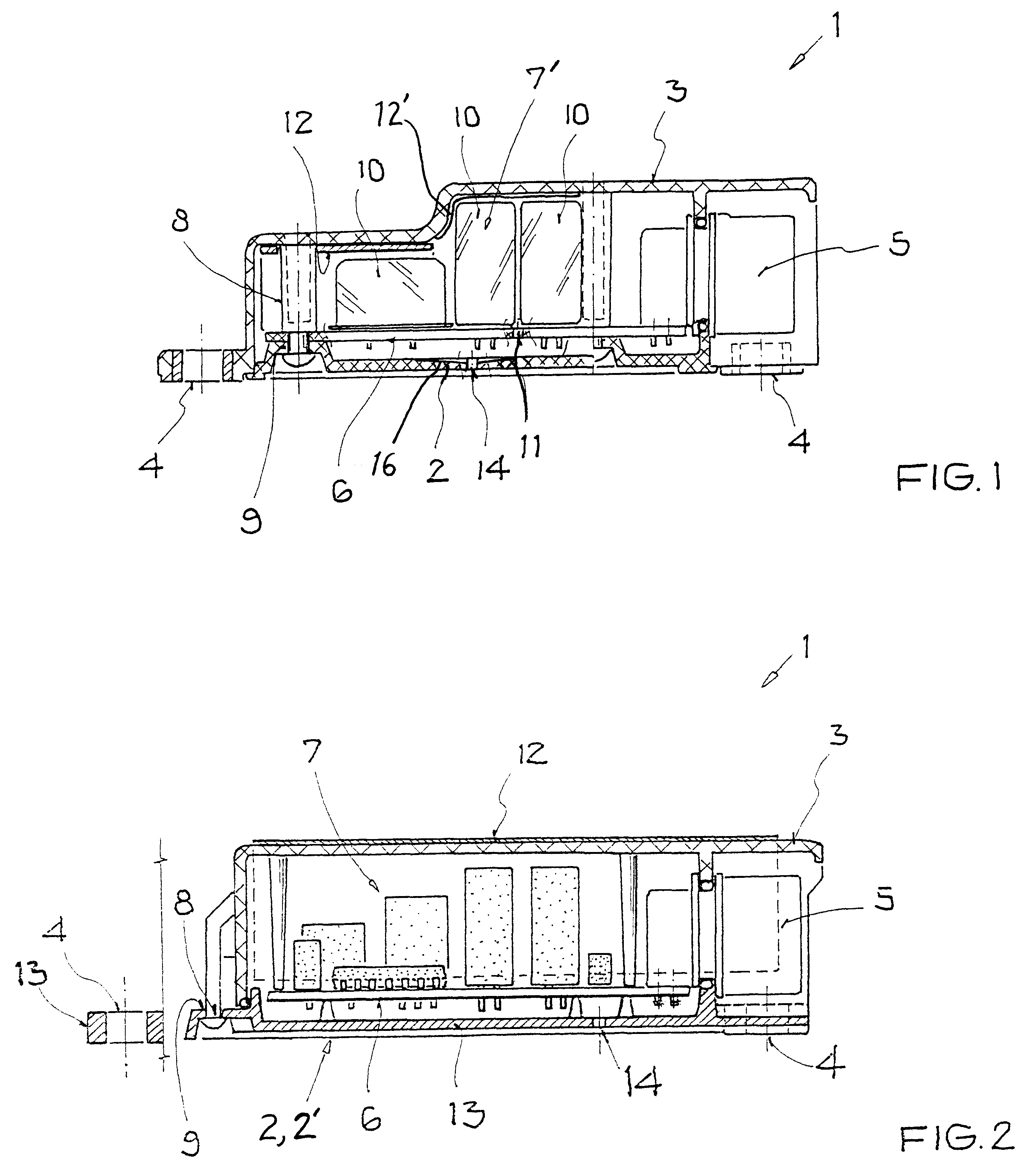
Both FIGS. 1 and 2 respectively show a housing 1 that is predominantly made of plastic (e.g. at least 50% plastic, or even at least 60, 70 or 80% plastic), and that encloses an interior space therein to be protected against direct entry of water sprays or the like. The housing 1 includes a housing cover or lid 3 made of any conventionally known and suitable plastic, as well as a a housing floor 2 that may be made of metal or a plastic such as a fiber-reinforced composite plastic (e.g. fiberglass-reinforced composite). In order to mount and secure the housing 1 in a motor vehicle, for example using screws or rivets, suitable mounting lugs or eyes 4 are formed onto the housing cover 3. An electrical connector plug unit 5 is integrated into the cover 3.

A circuit board 6 with an assembly of electric and electronic components 7, 7'mounted thereon is arranged in the interior of the housing 1. Pins or studs 8 protrude from the housing cover 3 and engage suitable bushings 9 provided in the ...


PUM


Abstract

A housing for an assembly of electronic components mounted on a circuit board is predominantly made of plastic, and includes a plastic housing cover and a housing floor. Metal surfaces are provided in the housing to preferentially condense moisture from the air in the housing upon cooling, to avoid condensation on the circuit board or the electronic components. The metal surfaces may be a metal casing around an electronic component, a metallized layer deposited on an inner surface of the housing, a metal insert in the housing, a metal housing floor, or an additional metal floor plate adjacent to a plastic housing floor. A hydrophobic film enforces condensate droplet formation, and channels and drain holes drain the condensate droplets out of the housing. An encapsulating film is unnecessary on the electronic components, because condensation on these components is avoided.

Description

PRIORITY CLAIMThis application is based on and claims the priority under 35 U.S.C. .sctn.119 of German Patent Application 199 56 675.5, filed on Nov. 25, 1999, the entire disclosure of which is incorporated herein by reference.The invention relates to a plastic housing for receiving an assembly of electric and electronic components mounted on a circuit board, particularly providing protection against condensation of moisture on the electric and electronic components.BACKGROUND INFORMATIONIt has previously been typical to enclose electric and electronic components mounted on circuit boards within metal housings for protecting the electric and electronic assemblies from external damage, environmental elements, etc. It is recently becoming common to provide synthetic plastic housings instead of the metal housings for enclosing such electric and electronic assemblies, especially in the field of electrical and electronic systems for motor vehicles, in view of the reduced weight, reduced ...

Claims


Application Information

Patent Timeline
IPC IPC(8): B60R16/02H05K5/00B60R16/023
CPCB60R16/0239H05K5/0047
Inventor BAUR, RICHARDFENDT, GUENTERWOEHRL, ALFONSWOERLE, ENGELBERT
Owner DAIMLER AG
Learn More