

Automated acoustic micro imaging system and method
- Summary
- Abstract
- Description
- Claims
- Application Information
AI Technical Summary
Benefits of technology
Problems solved by technology
Method used
Image

Examples
Embodiment Construction
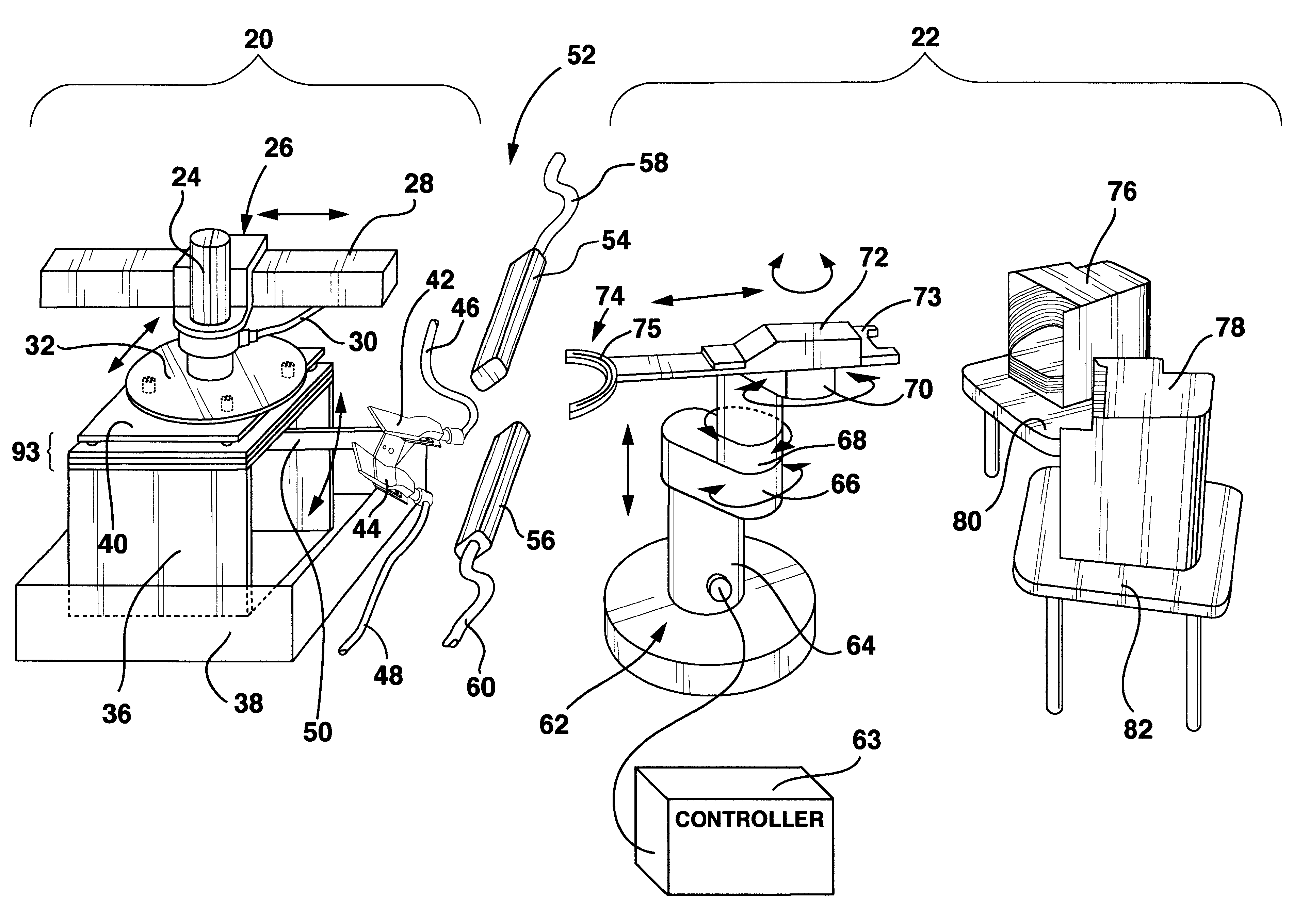
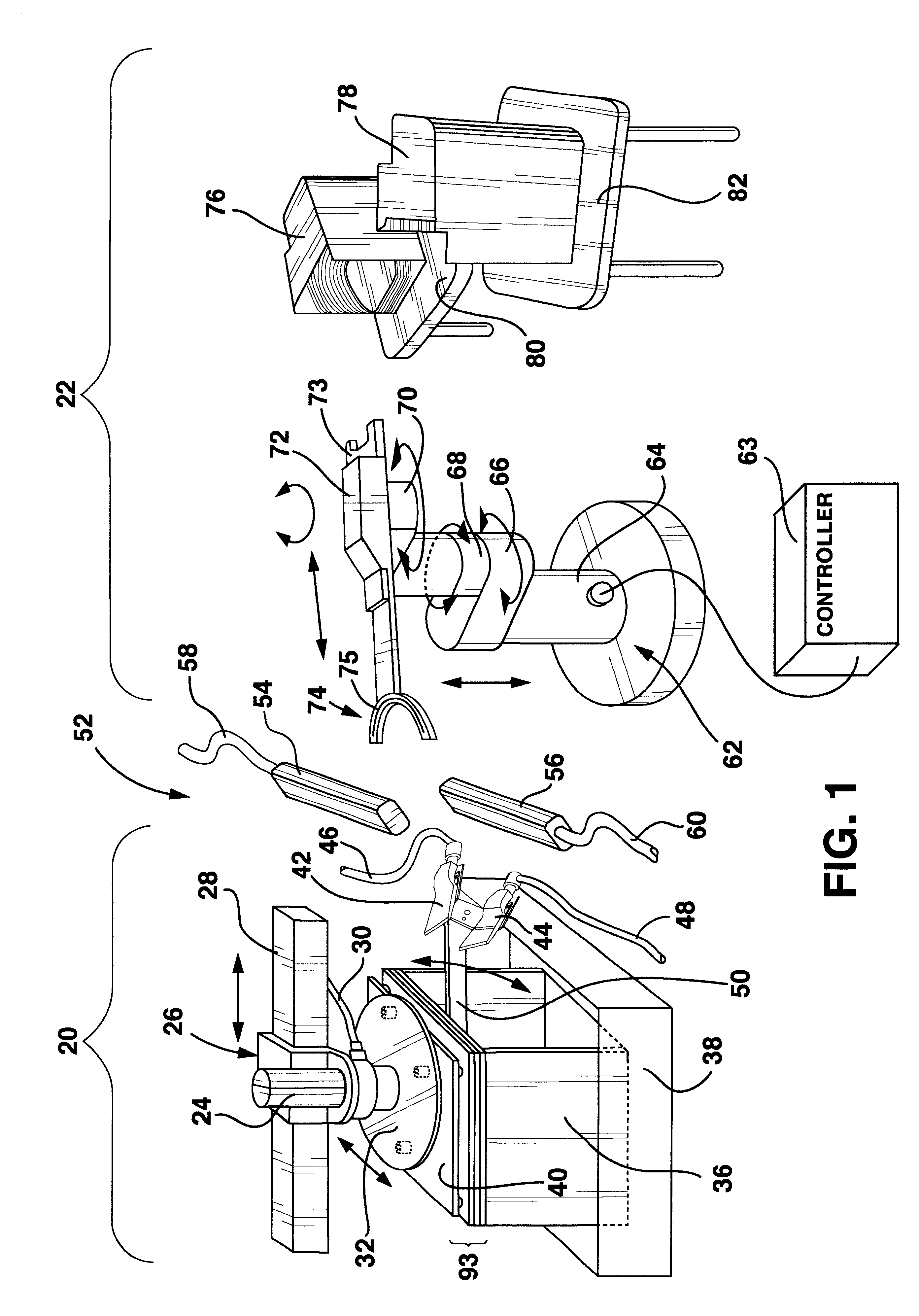
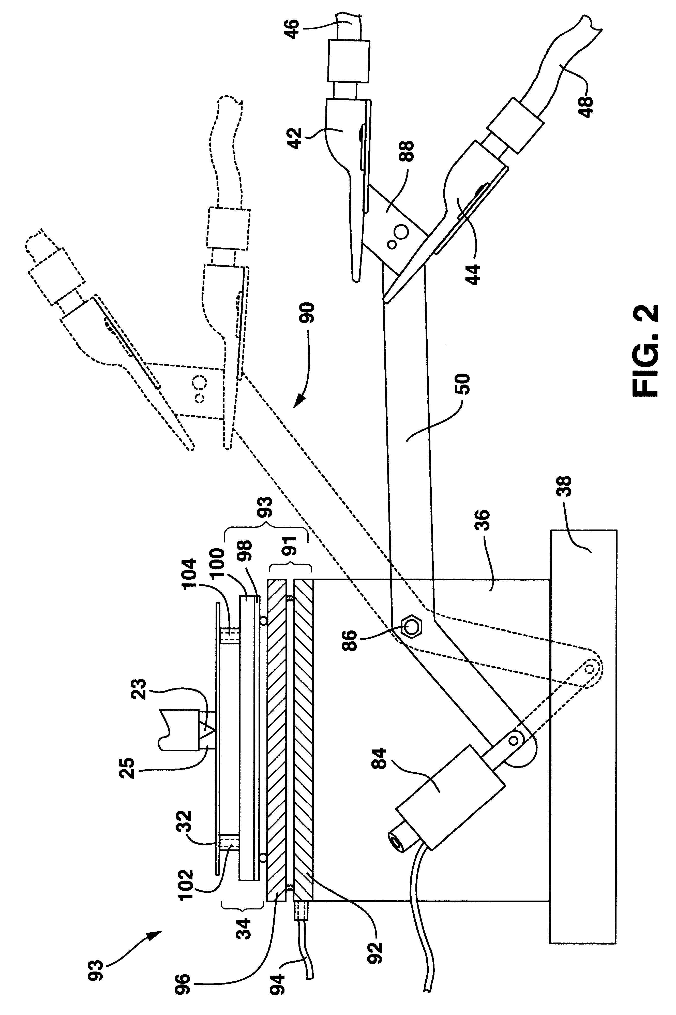
The present invention is directed to an automated acoustic micro imaging ("AMI") inspection system and method that enables the automated inspection of various part sizes and configurations in the hostile wet-environment of an AMI system. As used herein "robot" means any programmable computer-controlled mechanical for performing prescribed motion functions. "Kinematic" or "kinematic mount" means any arrangement wherein two structures are separably coupled in such a way that relative movement therebetween is uniquely constrained, with the assistance of gravity or other force, in all six degrees of freedom, namely X-axis, Y-axis, Z-axis, roll, pitch and yaw.
A preferred apparatus and method of execution of the invention is illustrated in the Figures, in which like reference numerals in different figures indicate like structure and function. The elements of the depicted execution will be first listed and identified with brief descriptive annotations where necessary to enlighten one skill...
PUM
 Abstract
Description
Claims
Application Information