
Optical compensatory sheet comprising transparent support, orientation layer and optically anisotropic layer

a technology of optical compensatory sheet and orientation layer, applied in the direction of thin material processing, instruments, chemistry apparatus and processes, etc., can solve the problems of inconvenient color and black and white images, defects are often observed at the interface between the domains, and conventional discotic liquid crystal molecules hardly give the optical characteristics required for optical compensatory sheets

Inactive Publication Date: 2002-10-08
FUJIFILM HLDG CORP
View PDF6 Cites 11 Cited by
  • Summary
  • Abstract
  • Description
  • Claims
  • Application Information

AI Technical Summary

Benefits of technology

The optically anisotropic layer having a high refractive anisotropy compensates a liquid crystal cell sufficiently even if the thickness is relatively small. Therefore, a relatively thin optically anisotropic layer can be used in an optical compensatory sheet. The alignment of discotic liquid crystal molecules can easily be controlled in the thin optically anisotropic layer. Accordingly, the alignment can be adjusted under the optimum conditions.
The alignment of discotic liquid crystal molecules can easily be controlled in the optical compensatory sheet of the invention. Therefore, the sheet can advantageously be used in not only a liquid crystal display of a STN mode (for which the applicants have first studied) but also other displays (e.g., a display of a TN mode) by adjusting the alignment according to the display mode.
The transparent support can be subjected to a surface treatment (e.g., glow discharge treatment, corona discharge treatment, ultraviolet (UV) treatment, flame treatment) to improve adhesion to a layer formed on the support (e.g., adhesive layer, orientation layer, optically anisotropic layer). An adhesive layer (undercoating layer) can be provided on the transparent support.
The hydrocarbon group preferably has a steroid structure, which not only lowers the surface energy of orientation layer but also shows an excluded volume effect. In cooperation with the lowered surface energy, the excluded volume effect makes the orientation layer vertically align liquid crystal molecules. In the present specification, the `steroid structure` means a cyclopentanohydrophenanthrene ring or a ring obtained by replacing a single bond of the cyclopentanohydrophenanthrene ring with a double bond. The hydrocarbon group having a steroid structure has preferably 18 to 100 carbon atoms, more preferably 19 to 60 carbon atoms, and most preferably 20 to 40 carbon atoms.
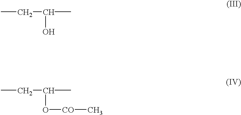
Polymerizable groups may be introduced into the denatured polyvinyl alcohol or (meth)acrylic copolymer. The denatured polyvinyl alcohol or (meth)acrylic copolymer having polymerizable groups and discotic liquid crystal molecules having polymerizable groups can be chemically combined along the interface between the optically anisotropic layer and the orientation layer, and thereby the durability of the optical compensatory sheet can be improved.

Problems solved by technology

The blue or yellow color is inconvenient for not only a black and white image but also a color image.
However, conventional discotic liquid crystal molecules form dual domain alignment, and hence defects are often observed at the interface between the domains.
Because of this, conventional discotic liquid crystal molecules hardly give optical characteristics required for an optical compensatory sheet.

Method used


Image

  • Optical compensatory sheet comprising transparent support, orientation layer and optically anisotropic layer
  • Optical compensatory sheet comprising transparent support, orientation layer and optically anisotropic layer
  • Optical compensatory sheet comprising transparent support, orientation layer and optically anisotropic layer

Examples


synthesis example 2

##STR16##

(2a) Synthesis of 4-(2-Hydroxyethyloxy)cinnamic Acid

The procedure of Synthesis Example 1 (1a) was repeated except that 4-chloroethylacetate was used in place of 4-chlorobutylacetate, to prepare the titled compound.

(2b) Synthesis of 4-(2-acryloyloxyethyloxy)cinnamic Acid

The procedure of Synthesis Example 1 (1b) was repeated except that the compound prepared above in (2a) was used, to prepare the titled compound.

(2c) Synthesis of 2,3,6,7,10,11-Hexakis[4-(2-acryloyloxyethyloxy)cinnamoyl]triphenylene (18)

The procedure of Synthesis Example 1 (1c) was repeated except that the compound prepared above in (2b) was used, to prepare the titled compound.

synthesis example 3

##STR17##

(3a) Synthesis of 4-(6-Hydroxyhexyloxy)cinnamic Acid

The procedure of Synthesis Example 1 (1a) was repeated except that 4-chlorohexylacetate was used in place of 4-chlorobutylacetate, to prepare the titled compound.

(3b) Synthesis of 4-(6-Acryloyloxyhexyloxy)cinnamic Acid

The procedure of Synthesis Example 1 (1b) was repeated except that the compound prepared above in (3a) was used, to prepare the titled compound.

(3c) Synthesis of 2,3,6,7,10,11-Hexakis[4-(6-acryloyloxyhexyloxy)cinnamoyl]triphenylene (22)

The procedure of Synthesis Example 1 (1c) was repeated except that the compound prepared above in (3b) was used, to prepare the titled compound.

synthesis example 4

##STR18##

(4a) Synthesis of 4-(8-Hydroxyoctyloxy)cinnamic Acid

The procedure of Synthesis Example 1 (1a) was repeated except that 4-chlorooctylacetate was used in place of 4-chlorobutylacetate, to prepare the titled compound.

(4b) Synthesis of 4-(8-Acryloyloxyoctyloxy)cinnamic Acid

The procedure of Synthesis Example 1 (1b) was repeated except that the compound prepared above in (4a) was used, to prepare the titled compound.

(4c) Synthesis of 2,3,6,7,10,11-Hexakis[4-(8-acryloyloxyoctyloxy)cinnamoyl]triphenylene (24)

The procedure of Synthesis Example 1 (1c) was repeated except that the compound prepared above in (4b) was used, to prepare the titled compound.


PUM

PropertyMeasurementUnit
twist angleaaaaaaaaaa

Abstract

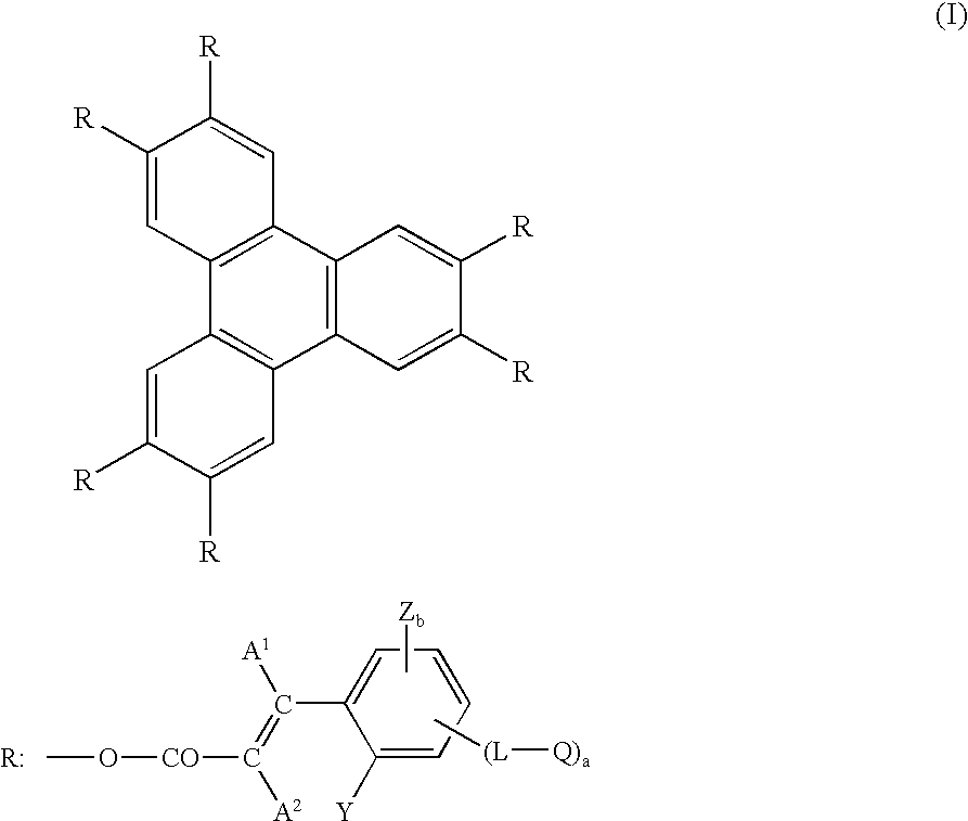
An optical compensatory sheet comprises a transparent support, an orientation layer and an optically anisotropic layer in this order. The optically anisotropic layer is formed from discotic liquid crystal molecules. The discotic liquid crystal molecule comprises a triphenylene nucleus and six cinnamoyl side chains. The optically anisotropic layer has a high refractive anisotropy in the range of 0.065 to 0.16.

Description

The present invention relates to an optical compensatory sheet comprising a transparent support and an optically anisotropic layer provided thereon and formed from discotic liquid crystal molecules. The invention also relates to a liquid crystal display equipped with the optical compensatory sheet.A liquid crystal display of an STN mode comprises a liquid crystal cell of an STN (Super Twisted Nematic) mode, two polarizing elements placed on both sides of the liquid crystal cell, and one or two optical compensatory sheets (phase retarders) placed between the liquid crystal cell and the polarizing element.The liquid crystal cell comprises a pair of substrates, rod-like liquid crystal molecules and an electrode layer. The rod-like liquid crystal molecules are provided between the substrates. The electrode layer has a function of applying a voltage to the rod-like liquid crystal molecule. Each of the substrates has an orientation layer, which has a function of aligning the rod-like liqu...

Claims


Application Information

Patent Timeline
Patent Type & Authority Patents(United States)
IPC IPC(8): C09K19/32G02F1/13G02F1/13363
CPCC09K19/32G02F1/133632C09K2019/328Y10T428/1041G02F2413/105Y10T428/1036C09K2323/031C09K2323/03
Inventor NISHIKAWA, HIDEYUKIKAWATA, KEN
Owner FUJIFILM HLDG CORP
Learn More