As a result, the leading and trailing ends of the steel sheet are not cooled satisfactorily and the quality of the material often become defective, which may lead to a reduction in product yield.
As a result, the time taken to roll the entire steel sheet is longer than the time it would have taken to roll the steel sheet from the leading end to the trailing end at the normal,
constant speed, so consequently the production efficiency is low.
Furthermore, there is an
idle time between rolling one steel sheet and rolling the next steel sheet, which further aggravates the production efficiency.
However, the roughing-down rolling used in this continuous hot rolling method is the same as that of batch rolling, so that planar, defective shapes known as tongues or fish tails are produced at the leading and trailing ends of each sheet bar.
Consequently, before joining sheet bars, such planar defects at the leading and trailing ends of each sheet bar must be removed before finish rolling.
Therefore, assuming n slabs are rough rolled, when the n sheet bars are joined, 2n portions (crops) are
cut off (the number of such crops is the same as for batch rolling), so a reduction in the yield concerned cannot be avoided.
In addition,. when joining sheet bars, portions to be joined must be heated, so defective material caused by the effects of heating, occur, although the effect is slight.
Also the strength of the joints in the sheet bars is adversely affected in the continuous hot rolling method and may be so low that the
production line might be stopped accidentally because a joint breaks during finish rolling.
When a slab is cast continuously,
cut losses are produced during slab
cutting and finishing, but the continuous hot rolling method gives rise to the same amount of
cut losses as the batch rolling method because the length of the slab is identical to that used in batch rolling.
The aforementioned unexamined Japanese patent publication No. 85305, 1984 describes that a slab with a thickness of about 200 mm can possibly be cast at a maximum speed of about 10 mpm using a rotary
caster, but no such result has been reported so far, therefore this
system cannot be applied in a practical hot rolling line aimed at
high productivity, at least at present.
In addition, this
system has such difficulties as cracks produced during
casting and the difficulty of applying the system to make a slab with a rectangular section.
The planetary mills and the cast rolling mills cited in the above-mentioned unexamined Japanese patent publications Nos. 106409, 1982 and 85305, 1984 are problematic in various aspects which will be detailed later, so these mills cannot be applied easily to a practical hot rolling process.
However, when a sheet bar is wound up once in an upended ended state and unwound in this rolling system, the sheet bar must be twisted through 90.degree., therefore a facility for twisting the sheet bar is needed.
Moreover, the approximate dimensions of a continuously cast slab with a weight of loot, for instance, are 1,000 mm wide.times.250 mm thick.times.50 m long, and when the slab is pressed to a sheet bar coil, the
diameter and weight of the coil is more than 4 m and 100 t, respectively, so that the coiling facilities become extremely large.
Also, when a sheet bar is coiled, the surfaces of the sheet bar rub against each other and are scratched, resulting in flaws on the surface, and a hot rolled steel sheet with a good
surface finish can no longer be manufactured, which is another problem associated with this rolling system.
In a normal roughing mill, the heat lost to the press rolls is greater because of the long length of material in contact with the rolls.
Consequently, a considerable amount of the heat contained in the hot slab before the beginning of rolling is lost during a conventional rough rolling process known in the prior art.
As a result, in a system with a line of conventional hot rolling mills, it is difficult to maintain the temperature of the material at the beginning of finish rolling, in particular for a rolling process for manufacturing a
thin sheet with a thickness of 2 mm or less, the temperature of the material decreases considerably during the finish rolling process, so that it is sometimes difficult to maintain the temperature of the material above the Ar3 point at the outlet of a finish rolling process.
To solve these problems, according to the prior art, a rolling system in which the heat loss is kept to a minimum by rough rolling the material at a high speed was developed, but this rolling system cannot be applied in practice because of the high equipment cost, in particular the driving system is very expensive.
A cast slab with a thickness of 100 mm or more is often accompanied by internal defects such as voids near the center part of the thickness of the slab, however, these defects cannot be easily eliminated by ordinary rough rolling because the slab is rather thick compared to the length of the contact arcs between rolls and the material, so the pressing strains cannot penetrate easily to the center part of the plate thickness.
Consequently, there is the fatal problem that the internal defects still remain at the end of a finish rolling process, in the worst case.
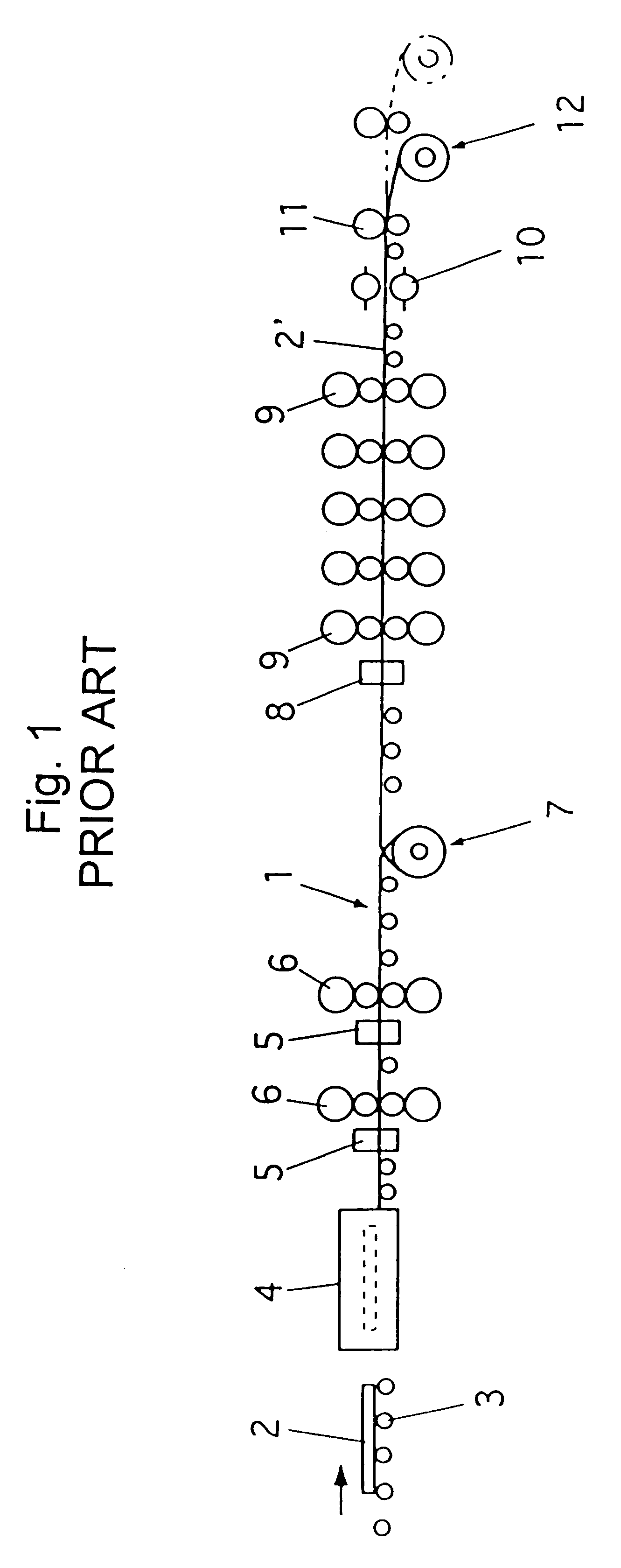
However, with the conventional rolling apparatus for a medium-thickness slab shown in FIG. 1, there are problems such as (1) to manufacture a slab with a thickness of about 20 mm, two rough rolling mills and an intermediate coiler for heating and holding are required, so the rolling line becomes so long that its cost is increased, (2) because a slab with a thickness of about 20 mm is rolled by rough rolling mills at a high speed in order to keep its temperature high, the rough rolling mills cannot be arranged to operate continuously (in tandem) with a finish rolling mill, (3) even when an intermediate coiler is provided, the slab must be reversed by coiling and uncoiling, therefore the temperatures of the leading and trailing ends and of both edges of the slab are not distributed evenly, so that the yield of the material to be pressed may often be low, and (4) consequently, very thin sheets (0.8 to 1.0 mm) for which there is a high demand cannot be manufactured with this apparatus.
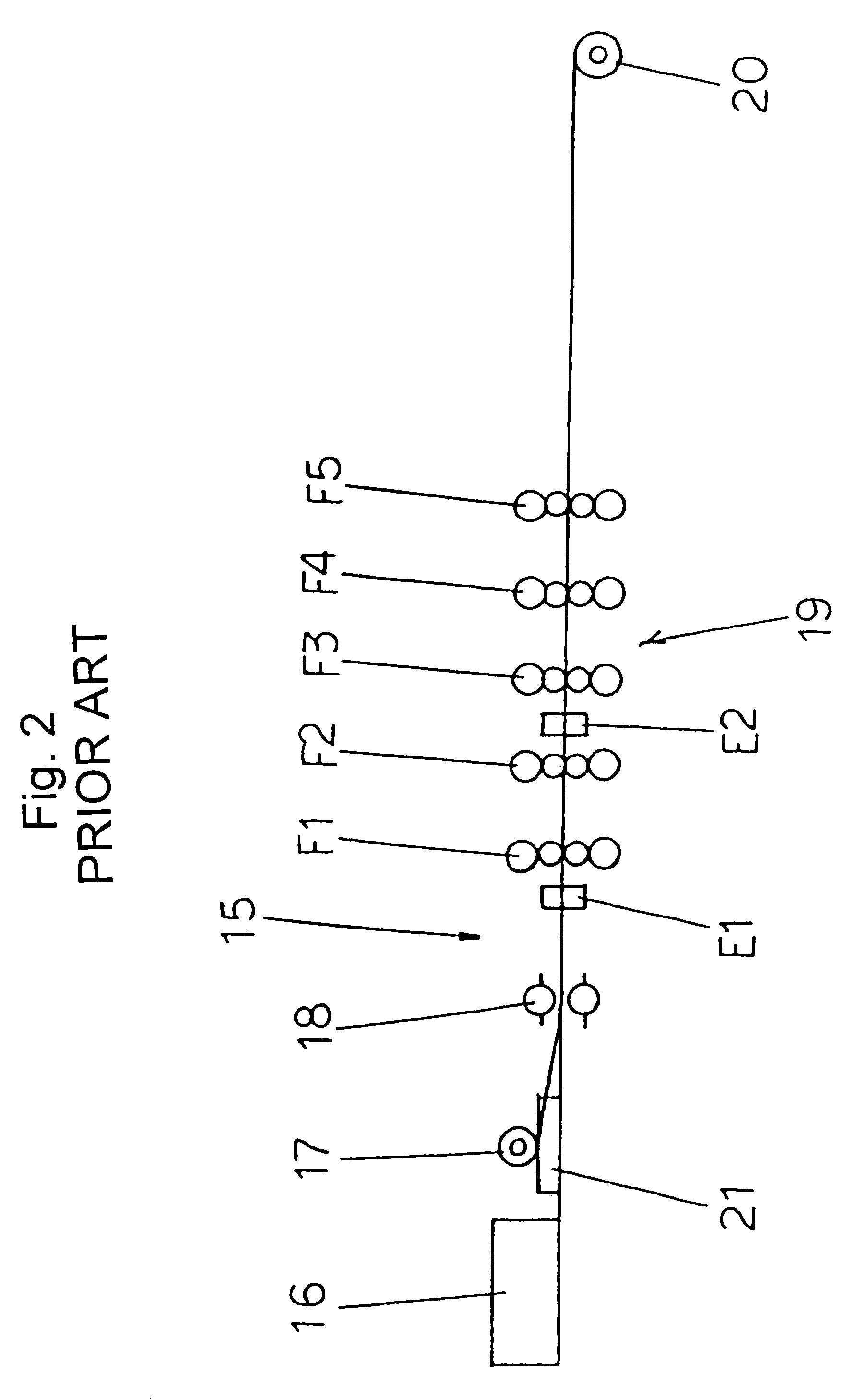
On the other hand, the conventional hot rolling apparatus shown in FIG. 2 provides a fairly short rolling line by omitting the group of rough rolling mills, but it is accompanied by various problems such as (1) when a slab is reverse rolled with a reverse rolling mill, the surface temperature of the material being rolled decreases so much that rolling becomes difficult, (2) the temperatures of the leading and trailing ends and the edges of the material being rolled are unevenly distributed, resulting in a low yield of the material being rolled, and (3) a coil box is required.
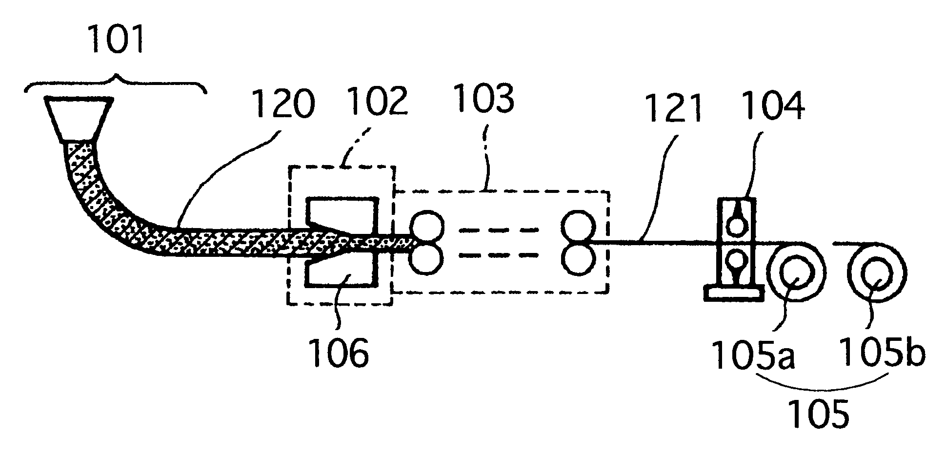
However, there was no such equipment that could roll a slab with an ordinary length and a long slab, by hot rolling to produce a
thin sheet, so there has been a demand for such equipment.
5. Moreover, with an ordinary rolling mill in which a material to be rolled is rolled between two work rolls, normally the
reduction ratio is limited to about 25%.
Consequently, a high
reduction ratio cannot be achieved when a material is rolled in a
single pass (for instance, reducing the material from about 250 mm to a thickness of 30 to 60 mm), therefore for this purpose, a tandem rolling system in which three or four rolling mills are arranged in tandem, or a reverse rolling system in which the material to be rolled is rolled backwards and forwards, are used in practice, however, there are problems such as that a long rolling line is needed.
However, with these rolling means, small
diameter rolls press the material to be rolled at a high speed, and are accompanied with various problems such as large impacts,
short life of bearings etc., unsuitability for
mass production facilities, and so on.
However, a conventional plate reduction press apparatus, an example of which is shown in FIG. 3 has a problem in that there are difficulties with the transfer speed of the material 31 to be pressed, although the apparatus can achieve high-reduction pressing in a
single pass.
Although the speed of feeding the material can be adjusted intermittently by changing the frequency of the pressing cycles, it is difficult to adjust the speed in
synchronism with a downstream finish rolling mill etc., continuously and precisely, because of the intrinsic structure of the plate reduction press apparatus, and even if such an adjustment can be achieved, the required pressing frequency and pressing loads (pressing forces) become excessively large when only the pressing frequency is used for the adjustment, which has given rise to problems such as large vibrations and a remarkable reduction in the life of the equipment.
However, when reverse rolling such as described above is carried out, space for pulling out the material 41 to be or being shaped must be prepared on both the upstream A and downstream B sides of the
transfer line in a group of rolling mills, therefore the equipment becomes so long and large that the material 41 to be shaped cannot be efficiently reduced in plate thickness, which imposes a practical problem.
The portion at the peak 65 of a bulge 62 is cooled early, so the edge cracks shown in FIG. 6 often appear, and even if there are no apparent cracks, the surface is liable to have cracks, and when the material is rolled, longitudinal flaws are produced after rolling.
These are called seam flaws.
These edge cracks and seam flaws are not desirable because they sometimes remain in the product.
However, since a long slab has been introduced following the development of the continuous
casting system, reversing pressing with a
sizing press or rolling with a roughing mill cannot be applied to a long slab.
Another problem is that when a slab is pressed and rolled simultaneously using a
sizing press and a roughing mill, the operations of the
sizing press and the roughing mill adversely affect each other.
When a slab is pressed and reduced in the lateral direction with an edger, any gaps, voids, etc. existing inside the edges of the slab, which may possibly cause cracks later, are compressed, so that even if the slab is later pressed and reduced in the direction of the thickness with a press
machine, cracks or flaws may not be produced so easily.
Because the cylindrical rolls compress any gaps etc. that if present in the slab, may cause cracks, by pressing the lateral edges of the slab, therefore even when the slab is later pressed and reduced in the direction of its thickness with a reduction press machine, cracks or flaws will not be produced so easily.

