
Forming metal foam structures

Inactive Publication Date: 2002-10-15
FORD GLOBAL TECH LLC
View PDF16 Cites 54 Cited by
  • Summary
  • Abstract
  • Description
  • Claims
  • Application Information

AI Technical Summary

Problems solved by technology

None of the above techniques are compatible with providing a preformed substrate with a foamed metal coating.
Among the techniques used to obtain thick coatings on metal members, are thermal-spray depositions, such as plasma jet or electric-arc metal spraying which presents several drawbacks: unfavorable high thermal and dynamic effects on the substrate; unfavorable changing of the physical properties of the coating during spraying; unfavorable phase transformation of the deposited particles; overheating of the substrate; and erosion or jamming of the spraying equipment.
However, the disclosure of such Patent did not teach how to achieve a foamed structure nor did it teach suitable parameters to obtain metal particle welding commensurate with the need for metal foaming.

Method used


Image

  • Forming metal foam structures
  • Forming metal foam structures
  • Forming metal foam structures

Examples


Embodiment Construction

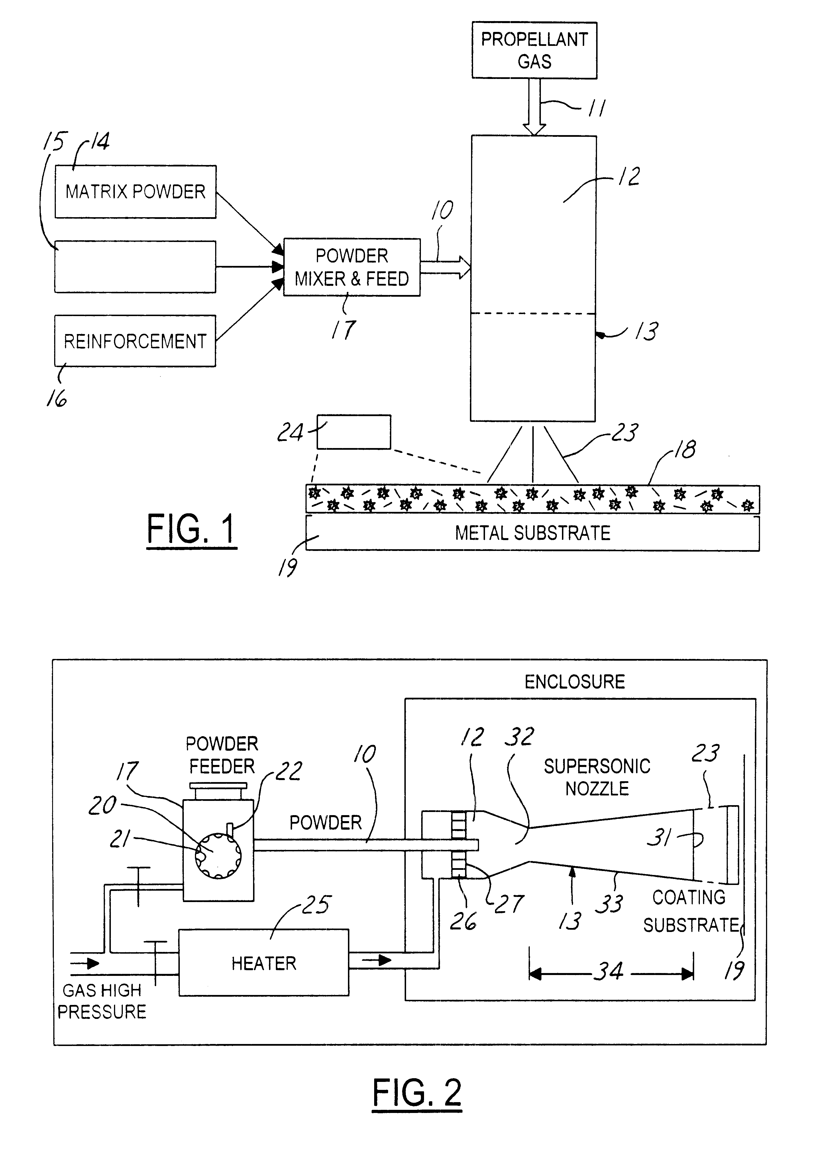
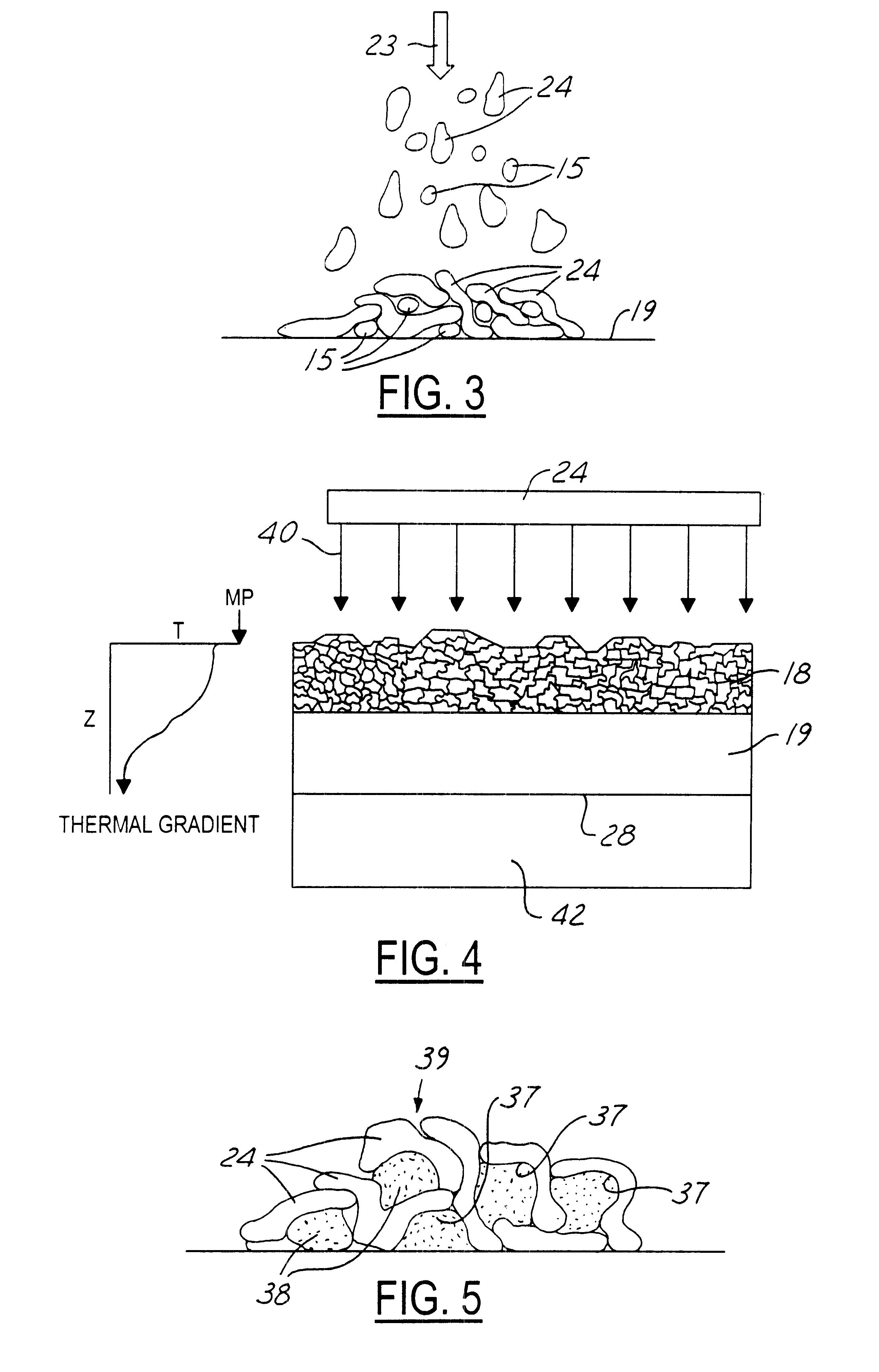
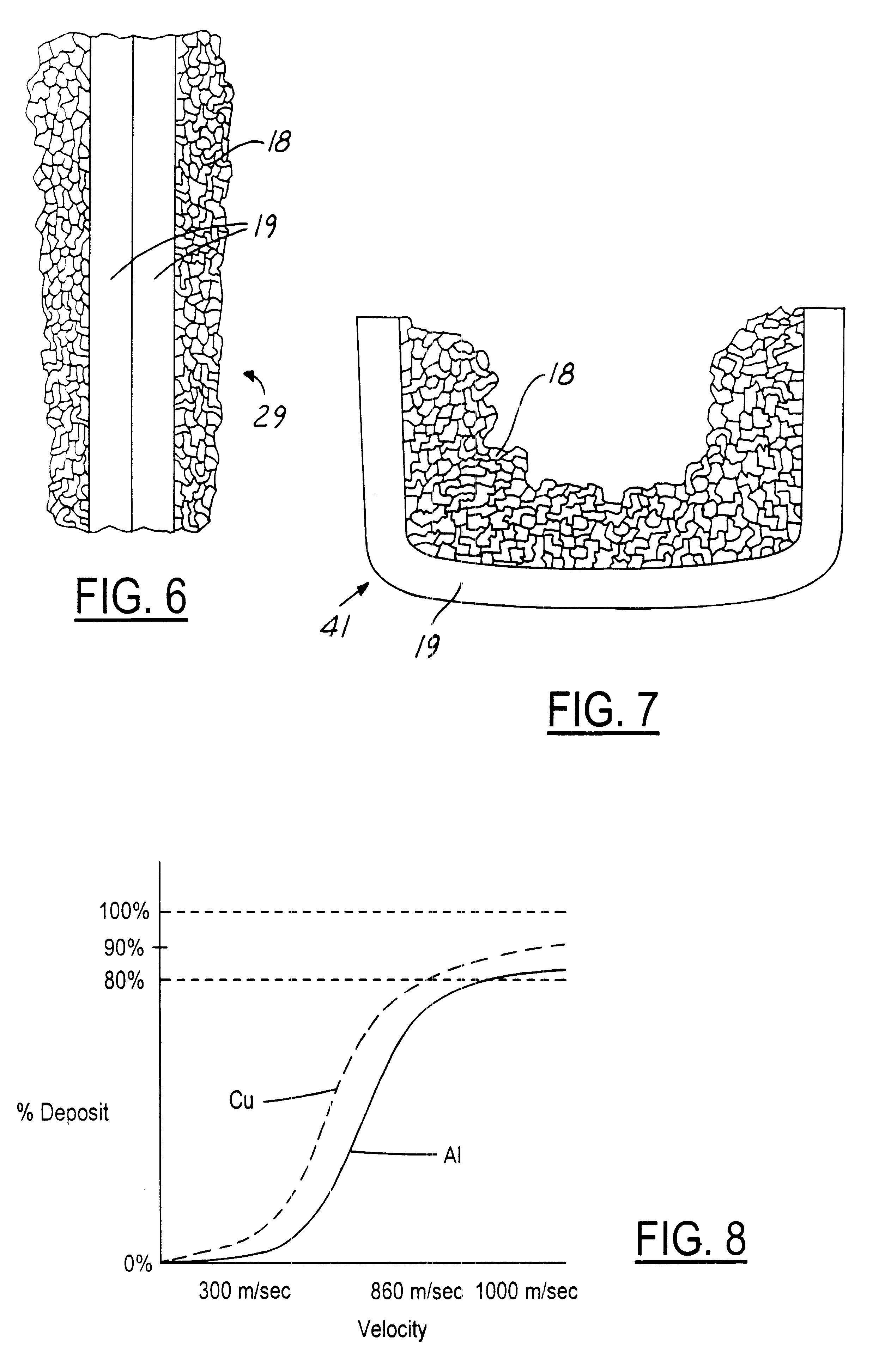
As shown in FIG. 1, the method begins by introducing a mixture of solid particles 10 and a carrier or propellant gas 11 to an ante-chamber 12 (entrance) of a supersonic nozzle 13 for projecting the mixture of particles and gas at a critical velocity to achieve a pressure-welded deposit 18. The solid particles 10 may be formed of a combination of solid metal particles 14, solid foaming agent particles 15, and any reinforcement particles 16 (such as Si, SIC, TIC, SiO.sub.2, graphite) separately added or incorporated directly in the matrix of the solid metal particles. The solid particles 10 are put into a particle mixer and metering feeder 17 where as shown in FIG. 2, the mixer blends the different particles together for a generally homogeneous mixture 24; the feeder has a cylindrical drum 20 with surface depressions 21 that accept a predetermined quantity of the solid particle mixture 24 for transfer, according to a powder controller 22, to the ante-chamber 12 of the nozzle. The tran...


PUM

PropertyMeasurementUnit
Pressureaaaaaaaaaa
Angleaaaaaaaaaa
Angleaaaaaaaaaa

Abstract

A method of fabricating a foamed metal structure using a powder supply of metal particles, comprising: (a) introducing the powder supply along with foaming agent particles into a propellant gas to form a gas / particle mixture stream; (b) projecting the mixture stream at a critical velocity of at least sonic velocity onto a metallic substrate to create a deposit of pressure-welded metal particles containing the admixed foaming agent; and (c) subjecting at least the coating of the substrate to a thermal excursion effective to activate expansion of the foaming agent while softening the metal particles for plastic deformation under the influence of the expanding gases.

Description

1. Technical FieldThis invention relates to the technology of making light-weight metal cellular structures and particularly to the use of cold-gas spraying techniques for achieving such metallic cellular structures.2. Discussion of the Prior ArtFoamed metals have been heretofore made by essentially adding a gas-evolving compound to molten metal and thereafter heating the mixture to decompose the compound causing the gas evolved to expand and foam the molten metal (see U.S. Pat. Nos. 3,940,262; 5,281,251; 5,622,542). To avoid adding the gas-evolving compound to a molten body of metal, solid particles of the metal, mixed with a gas-evolving compound, can be hot pressed or compacted and then subsequently heated near the melting temperature of the metal, or into the solidus-liquidus range of the metal, to create foaming for a cellular structure (see U.S. Pat. No. 5,151,246). Casting molten metal around granules which are then leached out leaving a porous structure is another method of ...

Claims


Application Information

Patent Timeline
IPC IPC(8): B22F3/11
CPCB22F3/1125B22F3/115B22F2999/00
Inventor POPOOLA, OLUDELE OLUSEGUNJAHN, RAYMCCUNE, ROBERT CORBLY
Owner FORD GLOBAL TECH LLC
Learn More