

Method of fabricating camshafts
a camshaft and cam shaft technology, applied in the direction of valve drives, manufacturing tools, machines/engines, etc., can solve the problems of limited dimensional accuracy of camshafts, cam lobes not properly engaging their associated movable members, and the method of fabrication is time-consuming and expensive, so as to reduce the size of the aperture
- Summary
- Abstract
- Description
- Claims
- Application Information
AI Technical Summary
Benefits of technology
Problems solved by technology
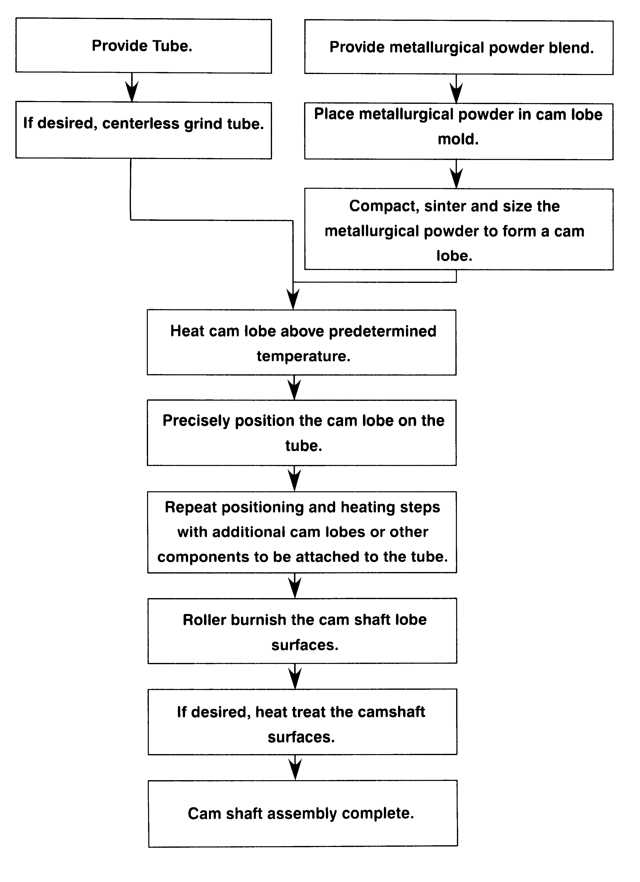
Method used
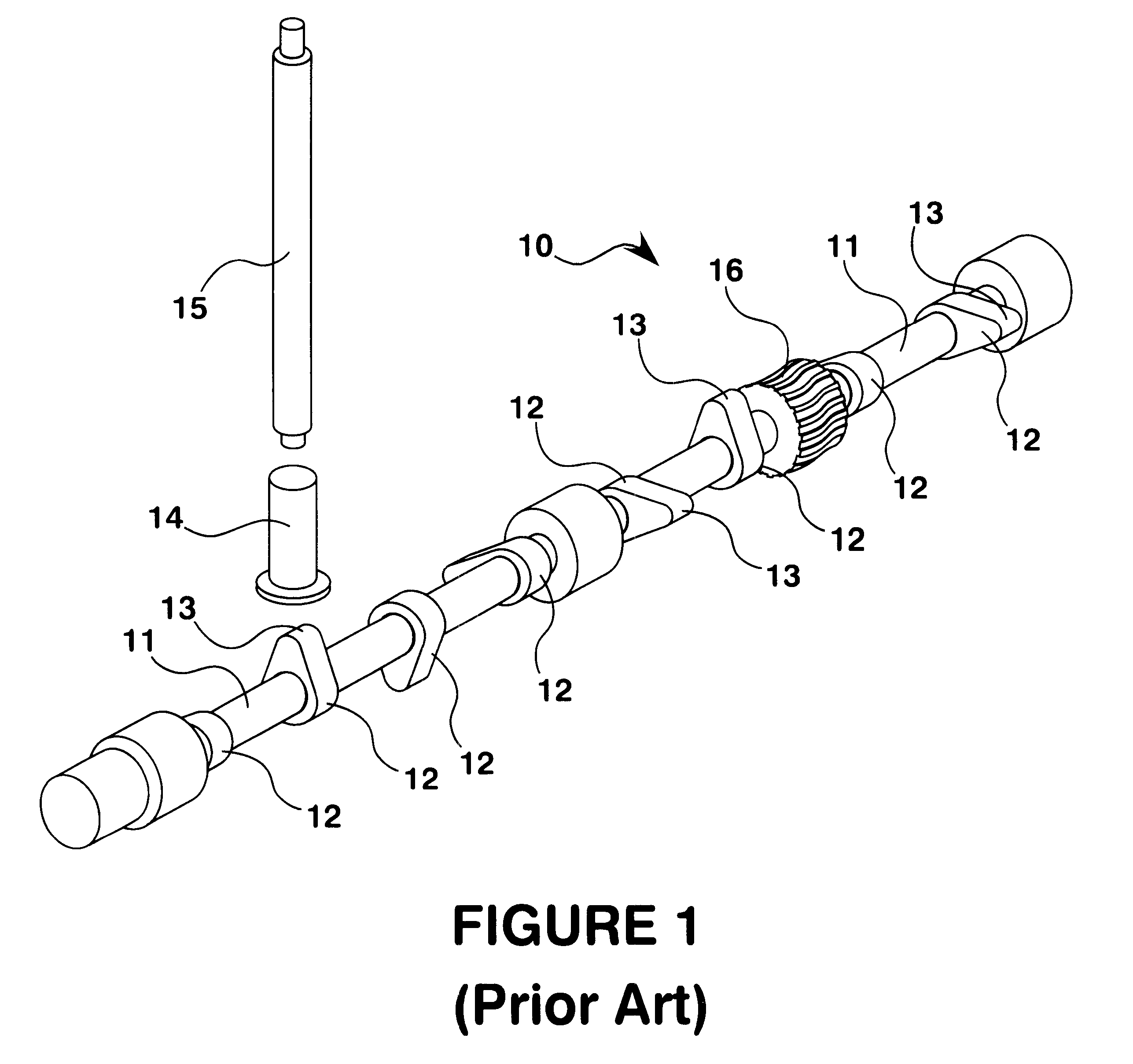
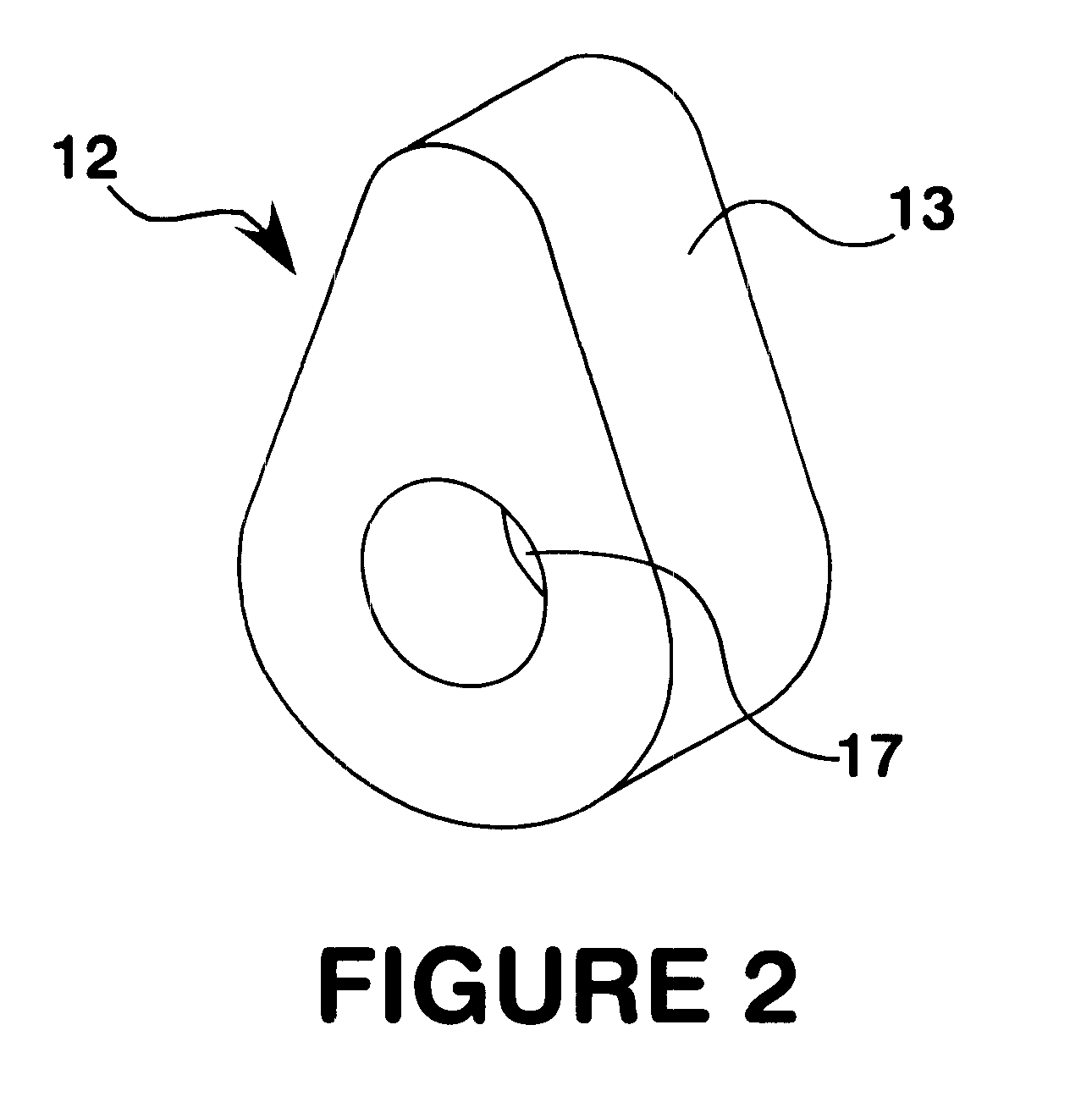
Image

Examples
example 1
Powder mixes 1-4 were prepared by blending metal powders, powdered graphite, and lubricant as follows:
Powder Mix 1: 97 parts (by volume unless otherwise noted) Kobelco 46F4 iron alloy powder; 3 parts Pyron 26006 copper; 0.6 parts Southwest Graphite 1652 graphite powder; and 0.65 parts Lanza Atomized Acrawax.
Powder Mix 2: 97 parts Quebec Metal Powders 4701 iron alloy powder; 3 parts Pyron 26006 copper powder; 0.6 parts Southwest Graphite 1652 graphite powder; and 0.6 parts atomized Lanza Acrawax.
Powder Mix 3: 100 parts Hoeganaes 85 HP iron alloy powder; 0.6 parts Southwest Graphite 1652 graphite powder; and 0.65 parts Lanza Atomized Acrawax.
Powder Mix 4: 100 parts Hoeganaes 4600V non-alloy powder; 0.6 parts Southwest Graphite 1652 graphite powder; and 0.65 parts Lanza Atomized Acrawax.
Cylindrical rolling contact fatigue specimens (approximately 0.562" OD.times.0.245" ID.times.0.625" long) were molded from each of the four powders at 50 tons / in..sup.2 (tsi). The specimens were then si...
example 2
A powder mix was prepared by blending 98.5 weight % Hoeganaes 4600V alloy powder (1.8% nickel-0.6% molybdenum-balance iron); 1.0 weight % Pyron 26006 copper powder; 0.5 weight % Southwest Graphite 1642 graphite powder; and 0.65 weight % Lanza Atomized Acrawax. Three samples of the powder mix were separately compacted at 50 tsi, and then sintered at 2050.degree. F. in an N.sub.2 -3% H.sub.2 atmosphere for about 30 minutes in a belt sintering furnace. The sintered specimens each included an aperture therethrough and were assembled about the outer surface of individual solid shafts of about 0.250 inch in diameter using a press fitting technique. The assembled specimens were mounted onto a lathe used for roller burnishing by retracting the expandable arbor of the lathe and then installing one of the 0.250 inch diameter shafts in its place. Thus, the shafts replaced the arbor during roller burnishing and simulated the installation of a cam lobe / cam shaft tube assembly on a roller burnish...
PUM
| Property | Measurement | Unit |
|---|---|---|
| temperature | aaaaa | aaaaa |
| temperature | aaaaa | aaaaa |
| density | aaaaa | aaaaa |
Abstract
Description
Claims
Application Information