Dual stage inflator

a stage inflator and stage technology, applied in the direction of pedestrian/occupant safety arrangement, vehicle components, weapons, etc., can solve the problems of gas-generating composition leakage outside the gas-generating assembly, disturbance of rattling noise, etc., to reduce weight, size, simple, compact and light-weight inflator

Inactive Publication Date: 2002-11-05
TALLEY DEFENSE SYST
View PDF68 Cites 115 Cited by
  • Summary
  • Abstract
  • Description
  • Claims
  • Application Information

AI Technical Summary

Benefits of technology

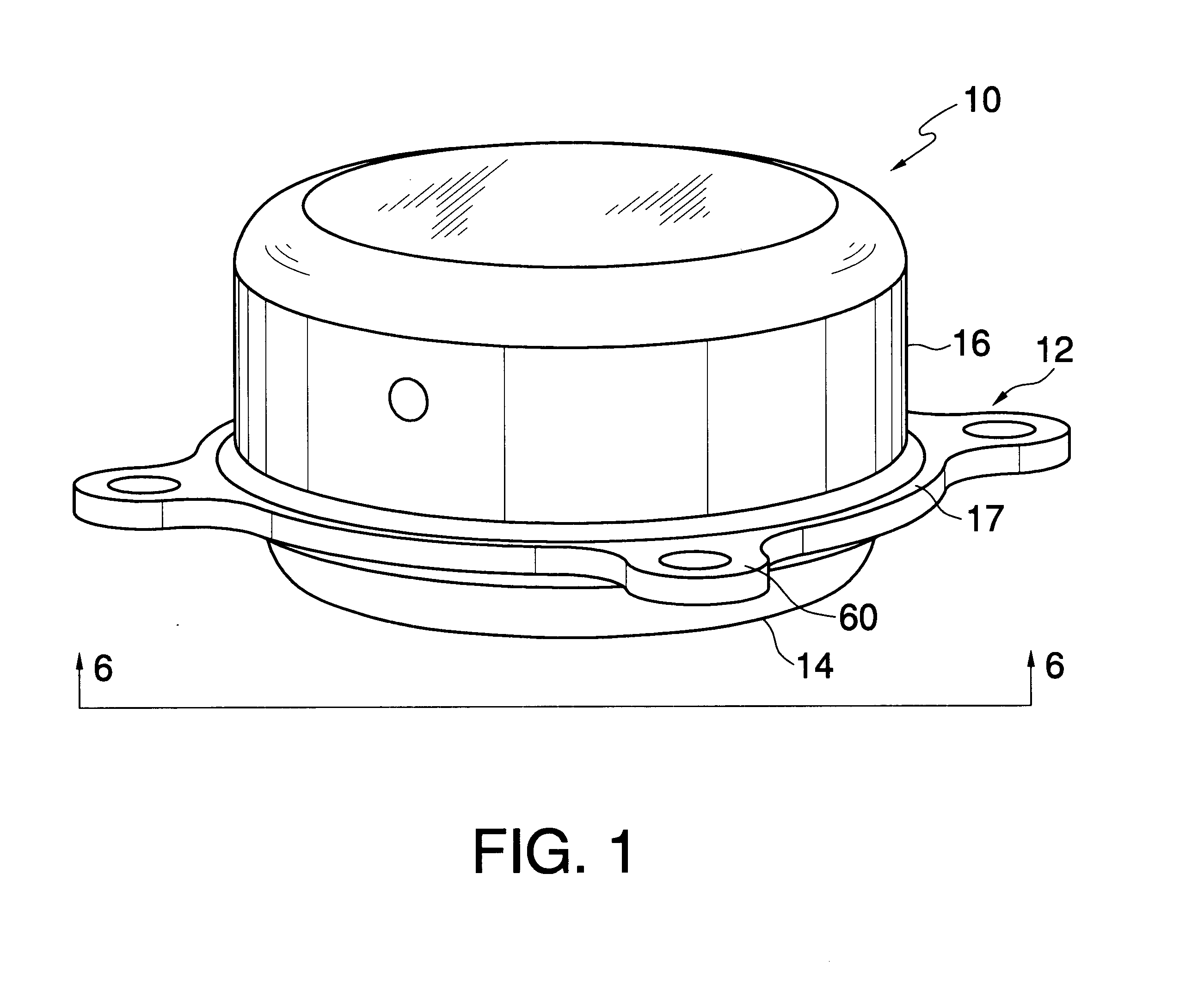
It is thus an object of the present invention to provide an inflator with reduced weight, size and with fewer geometric constraints on its design and packaging. It is a further object to provide a simple, compact and light-weight inflator. It is a still further object to eliminate the need for a filter in an inflator. It is another object to provide a gas-generating inflator which eliminates or at least reduces the size of internal structural members of the pressure vessel and their attachment means. It is a further object of the invention to provide a less costly inflator both in terms of fewer parts and fewer and less costly manufacturing operations to assemble and which yet may serve as a drop-in replacement for existing toroidal driver-side air bag inflators. Another object of the invention is to provide a dual stage driver inflator having a single pressure vessel that is capable of producing a modulated output with respect to the speed and force of an air bag deployment between a first minimum level and a second maximum level based upon sensor input relating to such factors as crash severity, seat-rack position, occupant weight and / or size, occupant location relative to the air bag, and whether or not the occupants are wearing seat belts.
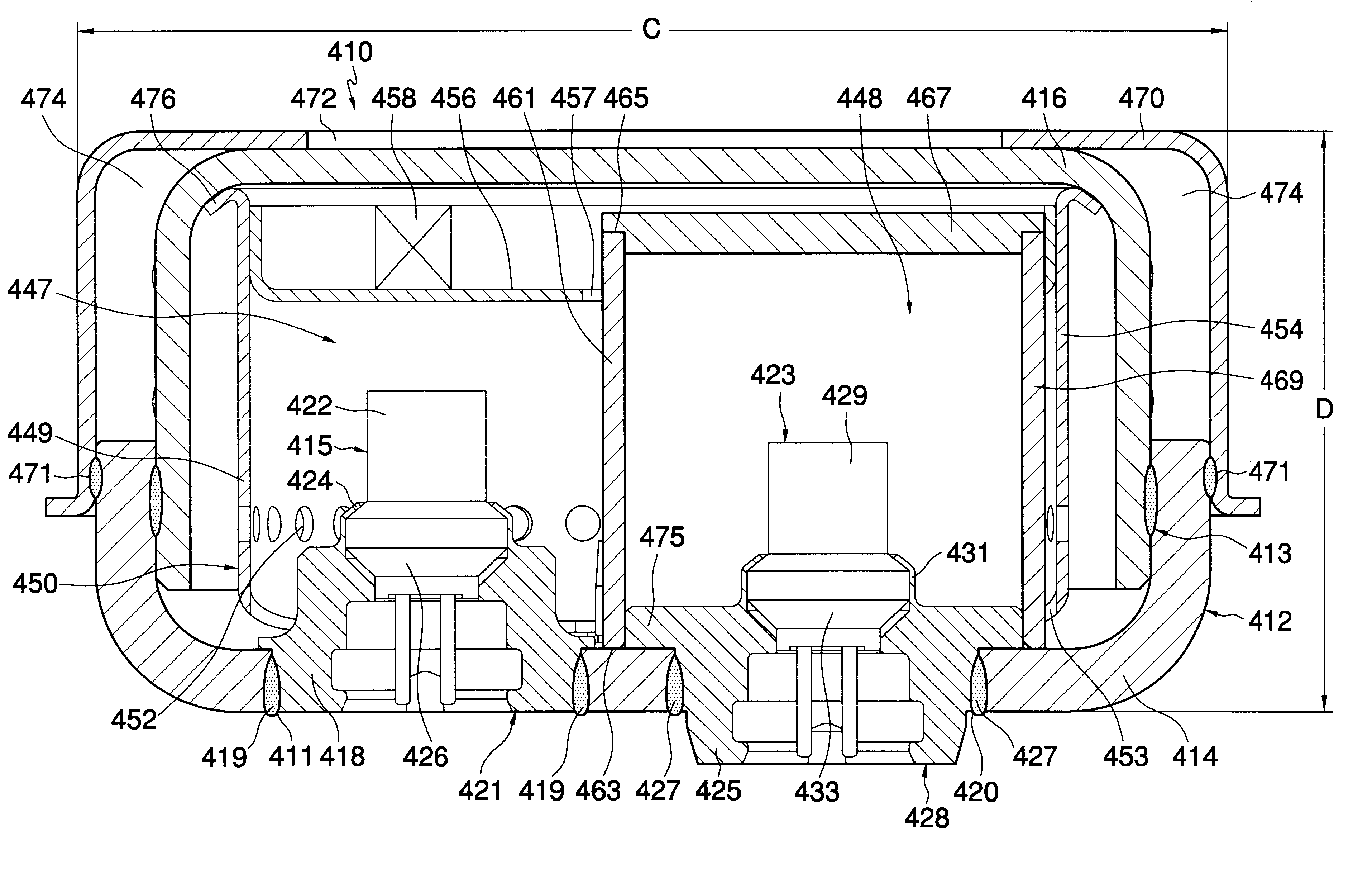
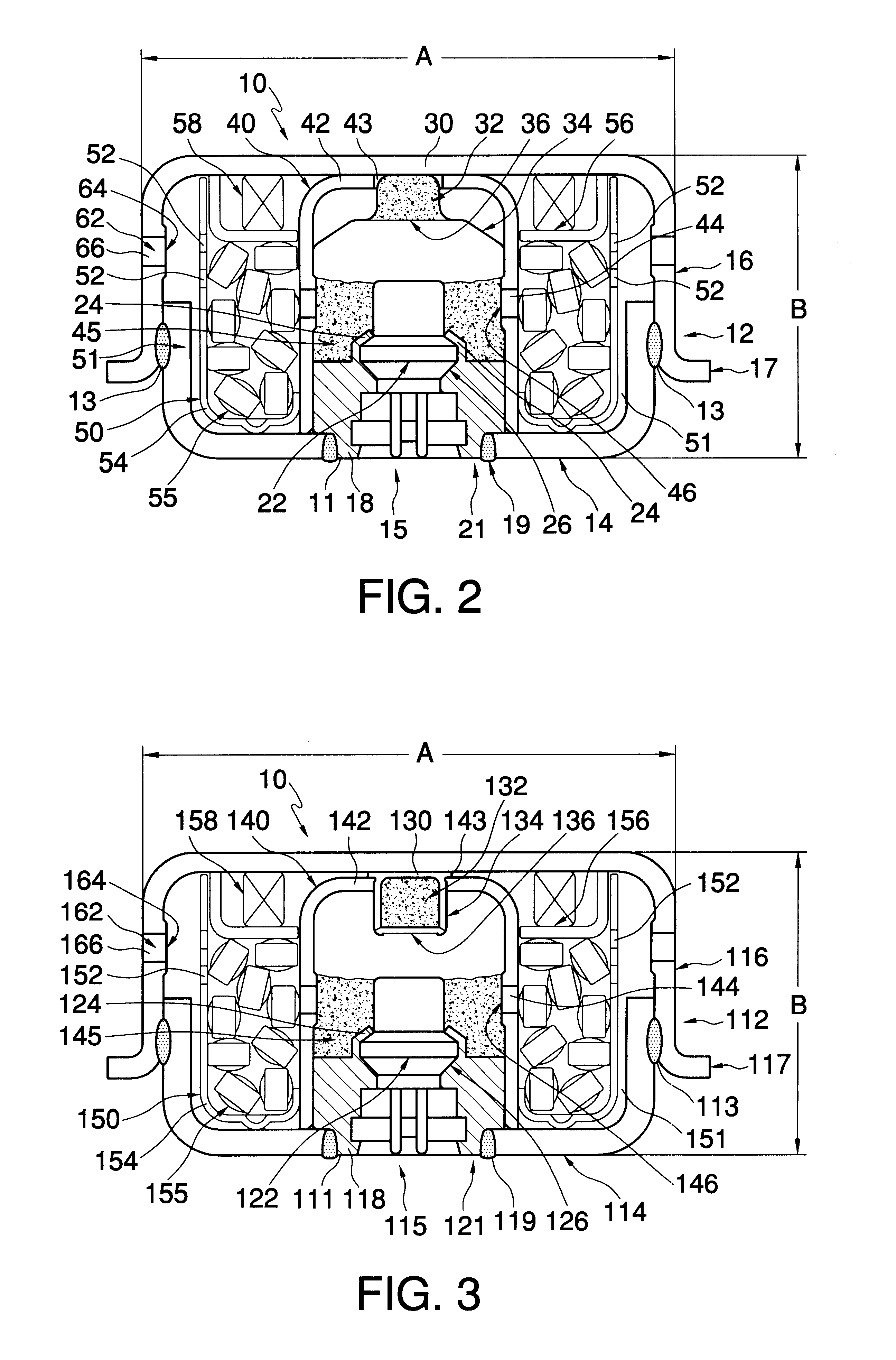
Thus, the first output level in combination with the second output level enables the production of a total gas output level modulated between dual outputs. That is the inflator is capable of operation in a first mode of initiating the first chamber only to produce a minimum gas output level, a second mode of initiating the second chamber only to produce a maximum gas output level, a third mode of initiating the first and second chambers simultaneously to produce the maximum gas output level, and a fourth mode of initiating the first chamber followed by the second chamber after a delay to produce an intermediate gas output level. Once the required gas output level is determined, the appropriate mode of operation is selected and the inflator is operated accordingly. Operation in either one of the second or third modes produces a maximum mass of gas pressure and a maximum mass flow rate, and the initiation of the first chamber followed by the second chamber after a delay produces an intermediate mass of gas and an intermediate mass flow rate. The ratio of the maximum mass of gas to the intermediate mass of gas is less than the ratio of the maximum mass flow rate to the intermediate mass flow rate. A further improvement in the level of modulation that may be achieved by the inflator can be achieved by increasing the number of chambers within the pressure vessel and controlling the amount of gas-generant in each chamber and the activation of the chambers.

Problems solved by technology

Preferably, the gas-generating cup assembly includes a spring-loaded lid to keep the gas-generating pellets from moving within the inflator which can cause disturbing rattling noises and also deterioration and crumbling of the gas propellant tablets and resulting leakage of the gas-generating composition outside of the gas-generant assembly.

Method used


Image

  • Dual stage inflator
  • Dual stage inflator
  • Dual stage inflator

Examples


example 1

The dual stage inflator shown in FIG. 7 was loaded with gas-generant tablets pressed into tablets having about 0.25 inch diameter, an average thickness of about 0.15 inches, and conolodated to a density of about 1.63 g / cc. The tablets were further coated with about 8% by weight of an ignition coating. The gas-generant tablets include about 58.5% by weight of 10 micron average particle size guanidine nitrate, 23.5% by weight 15 micron average particle size ammonium perchlorate, 17.8% by weight 10 micron average particle size sodium nitrate, and 0.2% by weight fumed silica. The ignition coating includes about 20.23% by weight of glycidal azide polymer polyol, commercially available from 3M Speciality Chemicals of Cottage Grove, Minn., 2.50% by weight SR444 (pentaerythritol triacrylate), commercially available from SARTOMER Company of Exton, Pa., 0.5% by weight HX868, commercially available from 3M Speciality Chemicals of Cottage Grove, Minn., and 0.5% by weight of a carbon black such ...


PUM

PropertyMeasurementUnit
angleaaaaaaaaaa
volumeaaaaaaaaaa
pressuresaaaaaaaaaa

Abstract

A non-hybrid pyrotechnic filterless inflator, i.e., gas generator, for an automotive passive restraint air bag having a generally discoidally-shaped pressure vessel having a diameter that preferably is greater than or about equal to its height formed of a cup-shaped closure cap and a base member and having at least one exhaust nozzle for directing gaseous products out of the inflator and into the air bag. The pressure vessel contains two separated and independently initiated initiator assemblies. By initiating either one or both initiator assemblies, the inflator can generate a modulated gas output between a first minimum output level and a second maximum output level in response to passenger and driver conditions.

Description

The invention relates to a gas-generating device or inflator suitable for rapidly inflating a flexible bag or filling a container to an elevated pressure. More specifically, this invention relates to a gas-generating device capable of modulated pressurization.Rapid gas-generating devices or inflators, as they are referred to in the art, have found widespread use. One use is in passive air bag restraint systems in order to reduce the large number of deaths and injuries occurring in automobile accidents annually. Air bags and inflatable belts for passive restraint systems are operatively associated with inflator devices which are generally activated by an inertial switch or sensor which detects rapid deceleration of a vehicle such as that which occurs upon impact between an automobile and another object. When the inertial switch is triggered, it causes an inflator to inflate a collapsed flexible bag or belt quickly which is deployed into a protective position in front of the occupant....

Claims


Application Information

Patent Timeline
Patent Type & Authority Patents(United States)
IPC IPC(8): B60R21/26B60R21/263B60R21/264C06C9/00C06D5/06
CPCB60R21/2644C06C9/00C06D5/06B60R21/264B60R2021/26064B60R2021/2633B60R2021/2648
Inventor LUDWIG, CHRISTOPHER P.WILLHELM, ROBERT S.BEDNARZ, JOHNHANSEN, GLADE L.MUIR, MARTIN J.SCAVEN, GREGORY J.
Owner TALLEY DEFENSE SYST
Why Eureka
Try Eureka