Direct-current arc furnace comprising a centric charging shaft for producing steel and a method therefor

a technology of centric charging shaft and arc furnace, which is applied in the direction of furnaces, charge manipulation, lighting and heating apparatus, etc., can solve the problems of increasing the stress on the refractory material, exhaust gas or dust cannot be controlled, and the iron oxidation of scrap metal cannot be controlled in hot gases

Inactive Publication Date: 2002-12-03
SMS SCHLOEMANN SIEMAG AG
View PDF13 Cites 6 Cited by
  • Summary
  • Abstract
  • Description
  • Claims
  • Application Information

AI Technical Summary

Problems solved by technology

During the melting-down process an arc deflection results which causes an increased stress on the refractory material.
During the charging process, the resulting exhaust gas or dust cannot be controlled.
Also, it is impossible to control in the hot g...

Method used


Image

  • Direct-current arc furnace comprising a centric charging shaft for producing steel and a method therefor
  • Direct-current arc furnace comprising a centric charging shaft for producing steel and a method therefor
  • Direct-current arc furnace comprising a centric charging shaft for producing steel and a method therefor

Examples


Embodiment Construction

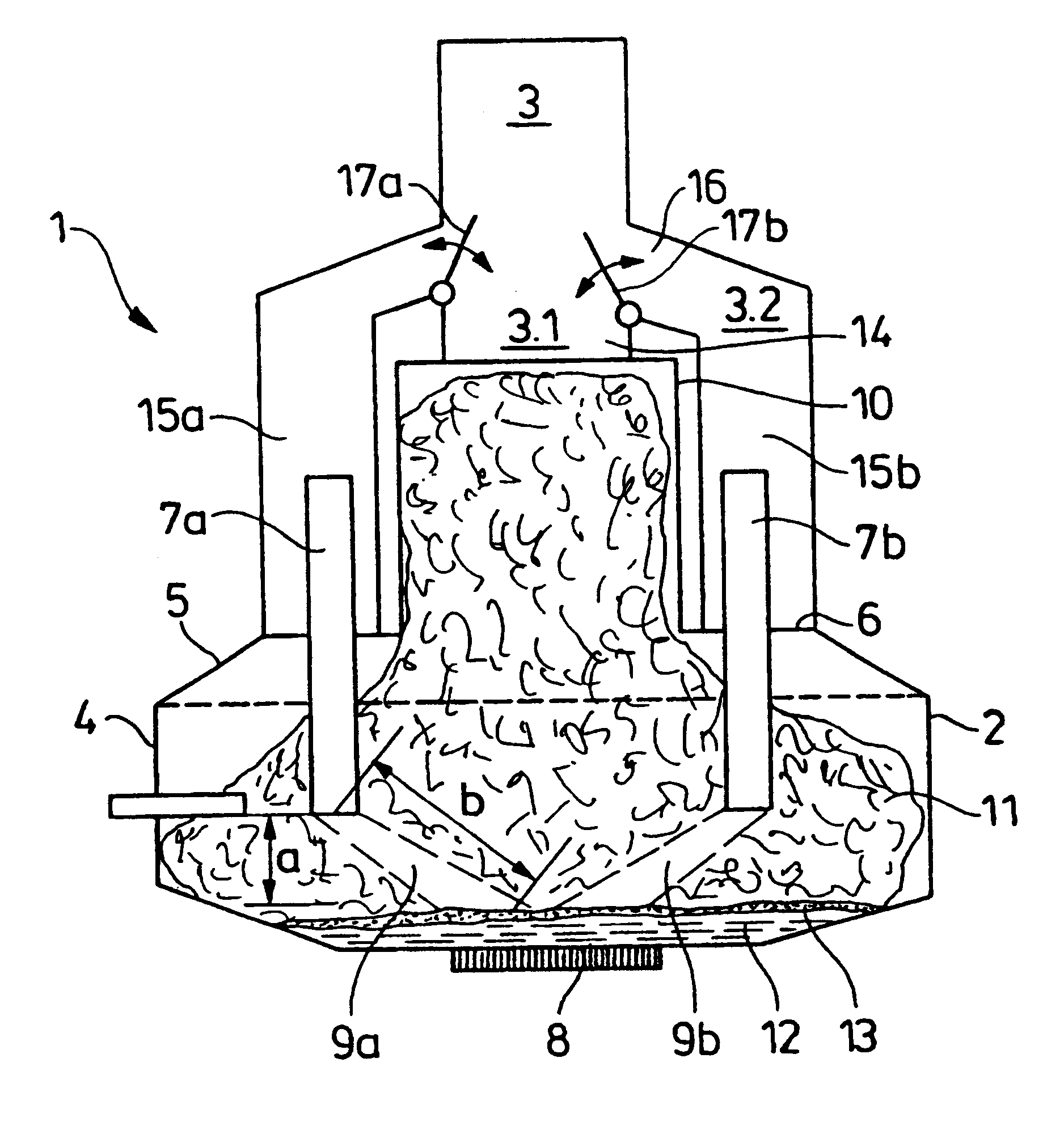
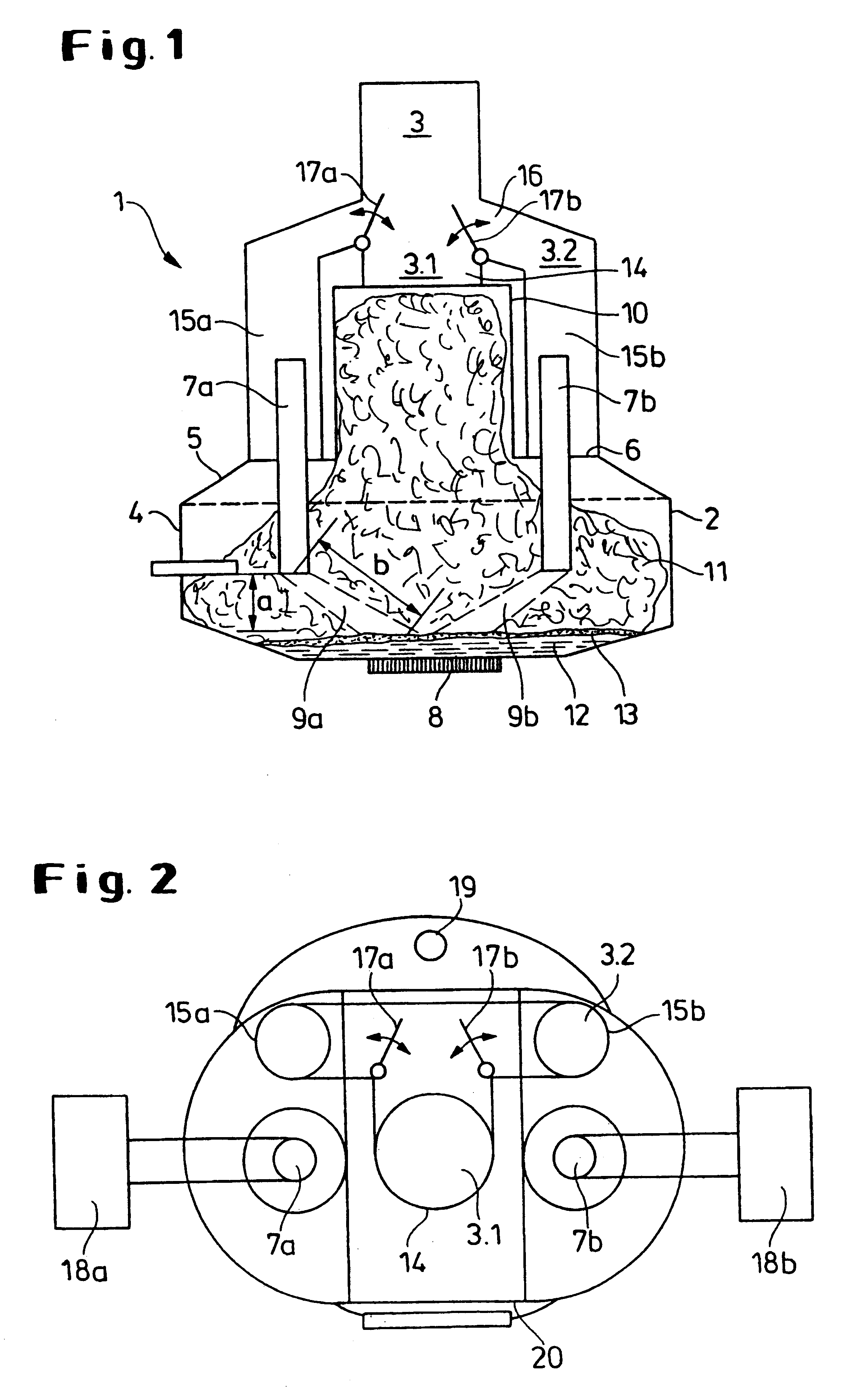
FIG. 1 shows a direct-current arc furnace 1 comprised of a furnace vessel 2 and an exhaust gas device 3. The furnace vessel 2 is comprised of a smelting area 4 and a lid 5. Via the openings 6 in+ the lid 5 two electrodes (cathodes) 7a,b are introduced into the vessel. On the bottom of the vessel between the two electrodes 7a, b a bottom electrode 8 is positioned. Two slantedly guided arcs 9a, b are the result. Their length, identified here with the letter b, is greater than the length of a vertically extending arc (length a) of known direct-current arc furnaces.

Above the furnace vessel 2 a shaft 10 is centrally arranged. Via this shaft 10, the furnace vessel 2 is filled with the melt-down material 11, in particular, scrap metal and sponge iron. The liquid steel resulting from the energy of the arcs 9a, b is identified with 12, while the slag is identified with 13.

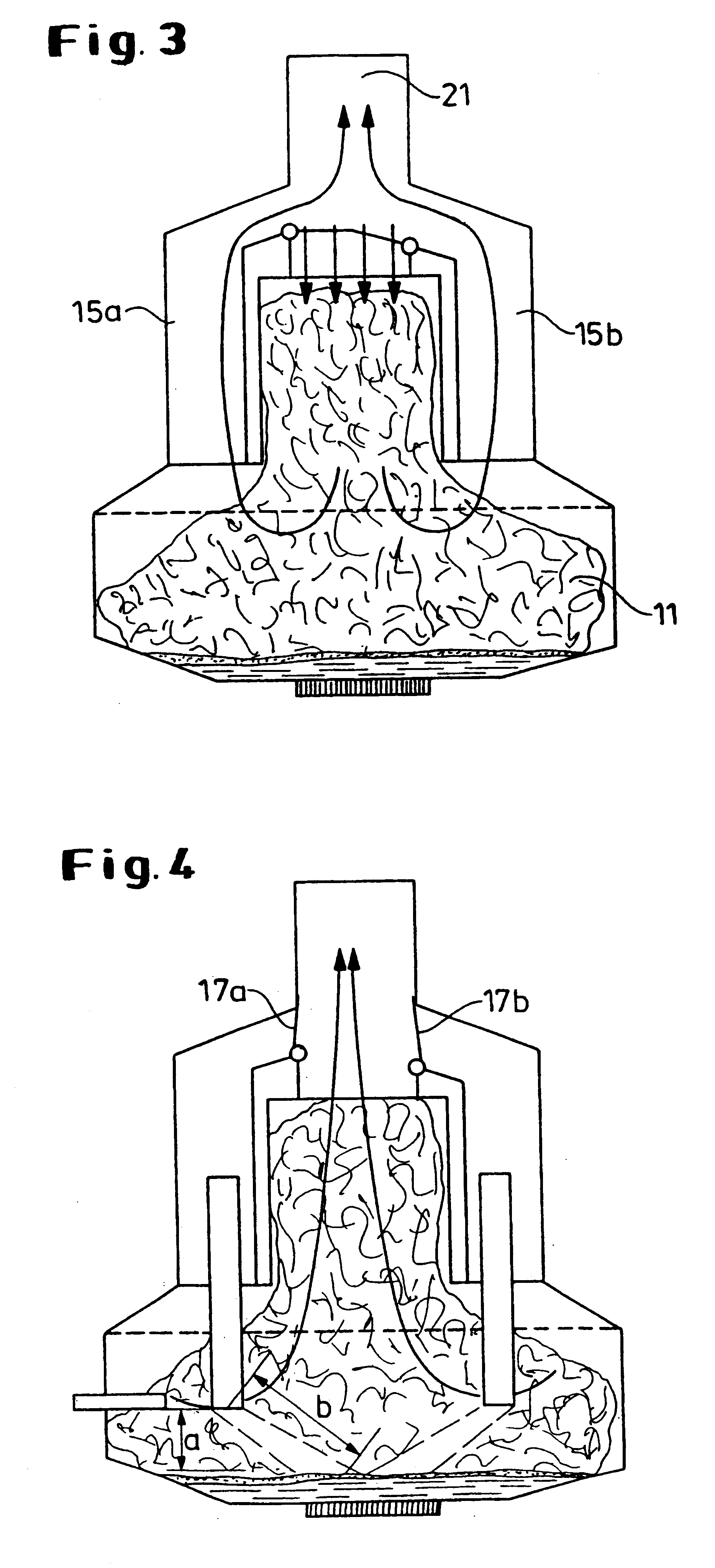
As an extension to the shaft 10 a shaft suction device 3.1 is provided. The shaft suction device 3.1 is comprised of a tu...


PUM

PropertyMeasurementUnit
Flow rateaaaaaaaaaa
Areaaaaaaaaaaa

Abstract

A direct-current arc furnace for producing steel has a smelting vessel with electrodes, tapping openings for the molten mass and slag, and a device for a direct removal of exhaust gases. The smelting vessel is extended upwardly by a central shaft for introducing melt-down material into the vessel. The extension of the central shaft forms a melt-down material column. A shaft suction device is provided as an extension of the shaft for removal of the exhaust gases during the smelting process. Adjacent to the shaft openings are provided in the upper part of the smelting vessel for receiving a vessel suction device for dust and/or gases resulting during the charging process of the melt-down material. The shaft suction device and the vessel suction device are connected to a common device and switching elements are provided for actuating only one suction device and/or adjusting a combination of the exhaust gas flows dependent on the charging and smelting process.

Description

1. Field of the InventionThe invention relates to a direct-current arc furnace for producing steel, comprising a smelting vessel with at least two electrodes for producing arcs as well as tapping openings for the molten mass and the slag. It further concerns a method therefor.2. Description of the Related ArtSeveral methods for producing steel are known. Essentially, two process routes are primarily in use: on the one hand, the steel production according to the conventional blast furnace-Bessemer converter route and, on the other hand, the production in an electric steel furnace.An electric steel furnace is conventionally a flat-cylindrical or oval vessel for melting down scrap metal or directly reduced iron (sponge iron). In the case of electric arc furnaces, the furnace is usually filled with the lid being pivoted out of the way, and the batch is melted down with the arc of the electrodes which penetrate through the lid into the furnace. Emptying of the furnace is realized, depend...

Claims


Application Information

Patent Timeline
IPC IPC(8): C21B13/00C21B13/12C21C5/00C21C5/52C21B13/02C21C5/56F27B3/08F27B3/10F27D17/00F27B3/18H05B7/18F27B3/04F27B3/26F27D11/08F27D11/10F27D13/00
CPCC21B13/026C21B13/12C21C5/5229C21C5/565F27B3/085F27B3/186F27D17/003Y02P10/20C21C5/527F27D11/10F27D3/14
Inventor PLESCHIUTSCHNIGG, FRITZ-PETERWU, WEI-PING
Owner SMS SCHLOEMANN SIEMAG AG
Why Eureka
Try Eureka