Method and apparatus for determining the location of an occupant of a vehicle

a technology for determining the location of an occupant and a vehicle, which is applied in the direction of height/levelling measurement, electric devices, lighting support devices, etc., can solve the problems of wide "blind spots" or "blind zones" on either side of the vehicle, limiting the view to either side, and affecting the alignment of azimuth angles

Inactive Publication Date: 2002-12-31
FREDRICKS RONALD J
View PDF13 Cites 69 Cited by
  • Summary
  • Abstract
  • Description
  • Claims
  • Application Information

AI Technical Summary

Benefits of technology

The light sources 206 and 208 may constitute high brightness LEDs encased within the housing 200 or may constitute the terminations of light pipes or cables from a remote common high intensity light source or from remote separate color high-intensity light sources. In the latter case, the end of the fiberoptic cable, suitable cleaved and lensed, would constitute a virtual light source within cavities of the housing 200. In any case, the right and left eye light beams 202 and 204 should be bright enough to be seen in daylight and distinctive in color while not so bright as to damage the driver's or passenger's eyes.
FIG. 18 illustrates a generic manner in which the driver or passenger of a vehicle can view the light beam pair 202 and 204. As shown in FIG. 18, the directions of the right and left eye light beams 202 and 204 are adjustable in tandem by the ...

Problems solved by technology

Even when properly adjusted, the bordering structure of the rear window limits the view to either side.
Improper adjustment of the sideview mirrors, particularly in azimuth angle results in wide "blind zones" or "blind spots" on either side of the vehicle.
Many drivers erroneously believe that correct azimuth angle alignment is achieved when the side panels of their own vehicle are reflected back to them along one edge of the exterior sideview mirrors when they are in their normal driving position.
All of these proposed solutions require either bulky assemblies, distort the image in the field of view so that the driver does not see all the potential safety hazards in correct prospective, or are complex electro-mechanical systems with intermittent or continuously running motors and subsequent noise and vehicle power drain.
Also, the imaged target on the side of the vehicle may not always be clearly visible due to road grime on the vehicle or simply because of low ambient lighting.
Finally, salient auxiliary mirrors and targets on the side of the vehicle large enough to be seen by the driver are anathema to automotive stylists.
Moreover, such approaches provide only a limited range of correct mirror adjustment and are not usable in all seat positions for all driver heights.
However, the illustrations of FIGS. 8 and 9 confirm that the rearward views attained at these nonstandard positions do widely vary and are not ideal.
As vehicle manufacturers seek to minimize sideview mirror size for styling and economy reasons, it is clear that this approach may well mislead drivers of non-standard height or seat position preference.
It is also proposed to mount the auxiliary turn signal lights to the sideview mirror structure as disclosed, for example, in U.S. Pat. Nos. 4,906,085, 5,014,167 and 5,207,492 Unfortunately these forward mounted, auxiliary turn signal lights may alert an overtaking driver in the adjacent lane too late to be totally effective, and may even encourage drivers to fail to properly set their sideview mirror azimuth angles...

Method used


Image

  • Method and apparatus for determining the location of an occupant of a vehicle
  • Method and apparatus for determining the location of an occupant of a vehicle
  • Method and apparatus for determining the location of an occupant of a vehicle

Examples


first embodiment

A summarized above, the first embodiment involves use of one or more fixed light sources emitting a respective light beam pair that is deflected by a reflector until the light beam pair is visible to the driver whereupon the driver's eye location may be derived. In a first variation illustrated in reference to FIGS. 1-5, each light source and reflector are associated with a vehicle sideview mirror. In a further variation illustrated in reference to FIGS. 11-15, a single light source and reflector are associated with a vehicle rearview mirror.

In the first variation of the first preferred embodiment illustrated in FIGS. 1-5, the a 'priori mathematical determination of the nominal blind spot direction with respect to the aforementioned mirror reference point on the mirror surface is used to mount a narrow wavelength light source emitting a light beam pair in a fixed relationship with respect to the vehicle left and / or right sideview mirror housing. When properly mounted in the mirror h...

second preferred embodiment

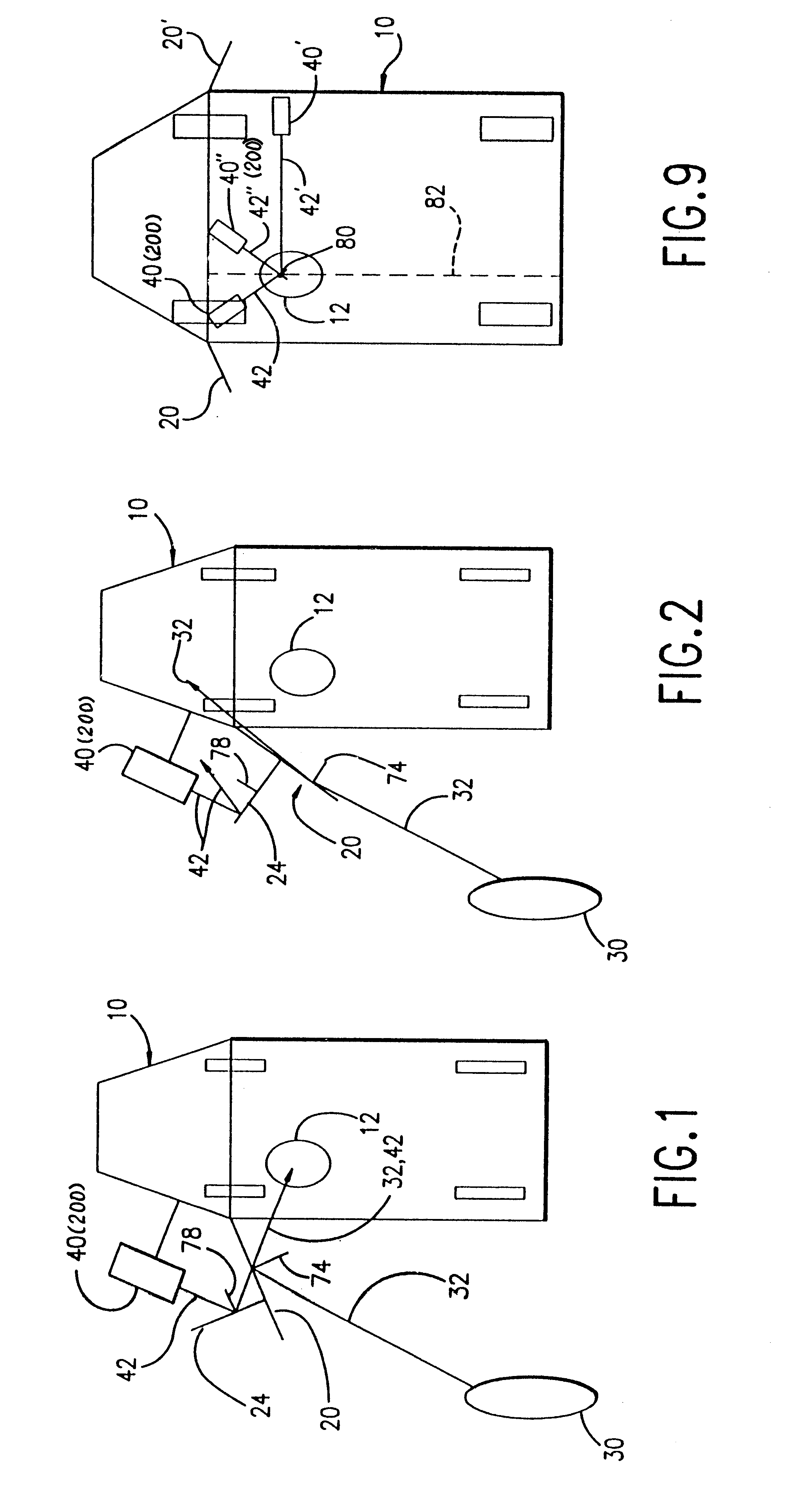
Before discussing the second variation of the first embodiment, attention is directed to the first variation of the second preferred embodiment and FIGS. 6 -8 wherein a light source 40 is associated with at least one of the vehicle sideview mirrors, as in the first variation of the first embodiment. In this second embodiment, the driver's manipulation of the joystick control 54 of FIG. 7 now directly adjusts the LED 40 (or other light source) light beam 42 direction, not the pitch and azimuth of the sideview mirror 20. In the system illustrated in FIGS. 6 and 7, the LED 40 is mounted for movement about pitch and azimuth axes within a sideview mirror assembly 27 in relation to a selectively light transmissive region 21 of the mirror 20. It should be noted that in a second variation of the second embodiment illustrated in FIGS. 9 and 10 and described in detail below, the LED 40 is mounted for movement about pitch and azimuth axes at a mounting point within the vehicle cabin. In either...

second embodiment

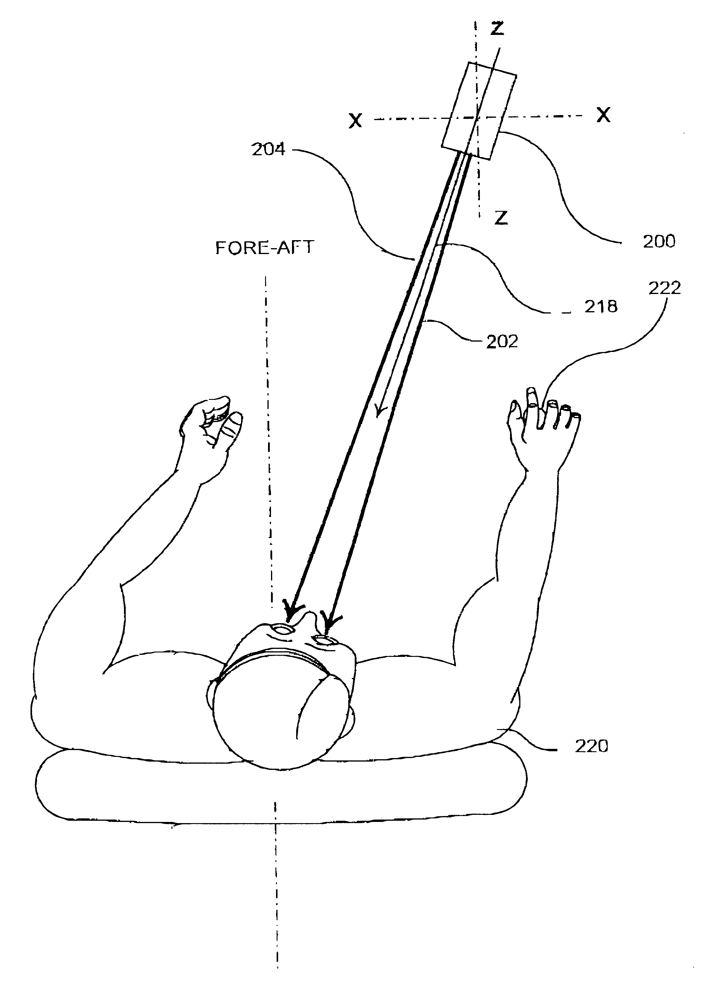
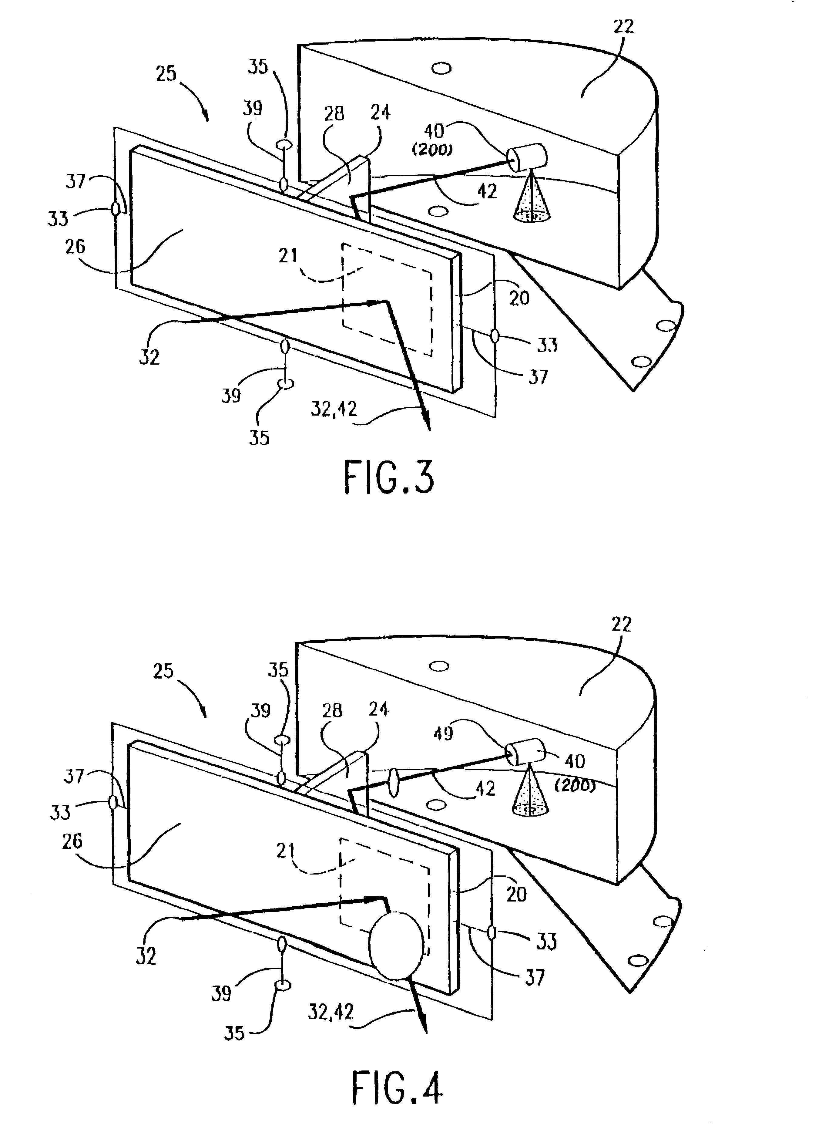
FIG. 6 shows a simplified mirror subassembly 25 of the mechanical components of this first variation of the second preferred embodiment of the invention with the LED 40 incorporated into the mirror subassembly 25 as in the embodiment depicted in FIG. 5. Note in FIG. 6, that the LED 40 is mounted on a set of LED pitch and azimuth gimbals 43 and 45, respectively, rather than directly mounted on the mirror housing 22. Also note that the LED beam 42 is directed toward the driver through the selectively light transmissive region 21 and not reflected off an auxiliary mirror. The latter is not necessary and would only complicate the mathematics involved in this The outer, LED azimuth gimbal 45 permits rotations of the LED 40, and hence LED light beam 42, about a vertical 49 to adjust for driver fore-aft seat position. The inner, LED pitch gimbal 43 allows for the LED 40 to be tilted up or down with respect to the driver's eye level about a horizontal axis 47.

In this first variation of the...


PUM


Abstract

A method and apparatus for use in locating the eyes of a vehicle driver or passenger in a vehicle for controlling vehicle systems including the positioning of vehicle sideview mirrors in relation to the driver's eyes to maximize the view of traffic on either side of the vehicle or the characteristics of vehicle airbag deployment. The location of a driver's or passenger's eyes is derived from the adjustment by the driver (or passenger, if capable of doing so) of adjustable light beam(s) emanating from light source(s) or illuminated indicia, until it (or they) intersect the driver's or passenger's eyes. From the angles of adjustment of the light beam(s) and other known coordinates of the vehicle, the location of the driver's or passenger's eyes or the target may be computationally derived as a set of Cartesian coordinates. The determined eye location of the driver may be used together with the known mounting locations of the driver's and passenger's sideview mirror assemblies to derive exterior sideview mirror pitch and azimuth adjustment signal sets correlated to the vehicle blind spots. The adjustment signals are applied to servo motors operating in a feedback control loop to correct the actual driver's side and passenger's side sideview mirror pitch and azimuth settings to properly reflect images of the driver's side and passenger'side vehicle blind spots to the driver's eyes. The determined eye locations of the driver and passenger may be also or alternatively employed in the control of the airbag deployment system and in other vehicle safety and comfort systems. The relative fore-aft distance away from the airbag and the height of the person or target can be computed, and airbag deployment force and/or duration adjusted to compensate for deviation from the standard height and fore-aft distance.

Description

1. Field of the InventionThe present invention relates to a method and apparatus for use in locating the eyes of a vehicle driver or passenger for controlling vehicle systems including the positioning of vehicle sideview mirrors in relation to the driver's eyes to maximize the view of traffic on either side of the vehicle and the characteristics of vehicle airbag deployment.2. Description of the Background ArtPassenger and commercial vehicles, e.g. automobiles and light trucks, are typically provided with a number of comfort features for the benefit of occupants and safety features and systems that are intended to help avoid collisions or to ameliorate the effects of collisions. At this time, virtually all enclosed vehicles, i.e. automobiles, sport utility vehicles, vans, trucks, etc., are provided with safety belts for use by occupants to strap themselves in. In addition, at least front seat driver's side and passenger's side explosively inflated airbags have become standard equipm...

Claims


Application Information

Patent Timeline
IPC IPC(8): B60R21/01B60R1/02B60R1/062B60R1/07B60R21/015G01B11/03
CPCB60R1/02B60R1/07B60R21/01554B60R21/01556B60R21/01552
Inventor FREDRICKS, RONALD J.
Owner FREDRICKS RONALD J
Why Eureka
Try Eureka