Substrate processing system and substrate processing method

a substrate processing and processing system technology, applied in the direction of total factory control, programme control, electric programme control, etc., can solve the problems of low system throughput, long time-consuming and laborious, and long time-consuming to raise the temperature of the heat processing uni

Inactive Publication Date: 2003-01-14
TOKYO ELECTRON LTD
View PDF10 Cites 48 Cited by
  • Summary
  • Abstract
  • Description
  • Claims
  • Application Information

AI Technical Summary

Benefits of technology

Thus, corresponding to a process procedure, a process start prediction time at which the process of each processing unit is started and a process completion prediction time at which the process of each processing unit is completed are calculated for each lot. Corresponding to the process start time and the process completion time, an optimum processing unit that optimizes the process for each lot is selected. Thus, after the process of each processing unit is completed, another process can be smoothly started with other conditions.
The calculation processing portion preferably selects optimum processing units that accomplish the process procedure in shorter time periods after the process completion prediction time for one lot until the process start prediction time for the next lot. Thus, the control amount of a processing unit until it accomplishes a process procedure (for example, the amount of power supplied to the heater of the heat processing unit) can be decreased. Consequently, the power consumption can be decreased. In addition, the process cycle time period in the regular state of the system can be shortened.
The processing units preferably include at least two heat processing units. The process procedure preferably contains a set temperature for each of the heat processing units for each lot. The calculation processing portion more preferably selects an optimum processing unit from a plurality of heat processing units corresponding to the set temperature. Thus, units that accomplish a set temperature in shorter time periods can be successively selected. Consequently, the amount of power supplied to the heating mechanism of each heat processing unit can be decreased.
The calculation processing portion calculates the process start prediction time and the process completion prediction time corresponding to a process completion prediction time for predicting a timing for processes for one lot and to a process cycle time period of each of the processing units. Thus, the process start prediction time and the process completion prediction time can be easily calculated. The process completion prediction time may be one of a first process completion prediction time after the first substrate of one lot is conveyed to a processing unit until the first substrate is returned to the loading / unloading portion, a second process completion prediction time after the first substrate of one lot is conveyed to a processing unit until all substrates of the same lot are conveyed to the processing unit, or a third process completion prediction time after the first substrate of one lot is conveyed to a processing unit until all substrates of the same lot are retuned from the processing unit to the loading / unloading portion.

Problems solved by technology

Such time differences cause the throughput of the system to lower.
However, in the case of for example a heat processing unit, if the unit is used as a pre-baking unit in the processes for the first lot and then used as a pre-baking unit in the processes for the second lot, assuming that the last temperature of the baking process for the first lot is 120.degree. C. and that the first temperature of the baking process for the second lot is 180.degree. C., it takes a long time to raise the temperature with the heater of the heat processing unit.
Thus, when processing units are assigned, since it takes a long time until they accomplish desired temperatures, the throughput of the system becomes low.
However, it takes a long time until an unused baking unit at the room temperature accomplishes a predetermined temperature.
Thus, the power consumption increases.

Method used


Image

  • Substrate processing system and substrate processing method
  • Substrate processing system and substrate processing method
  • Substrate processing system and substrate processing method

Examples


first embodiment

(First Embodiment)

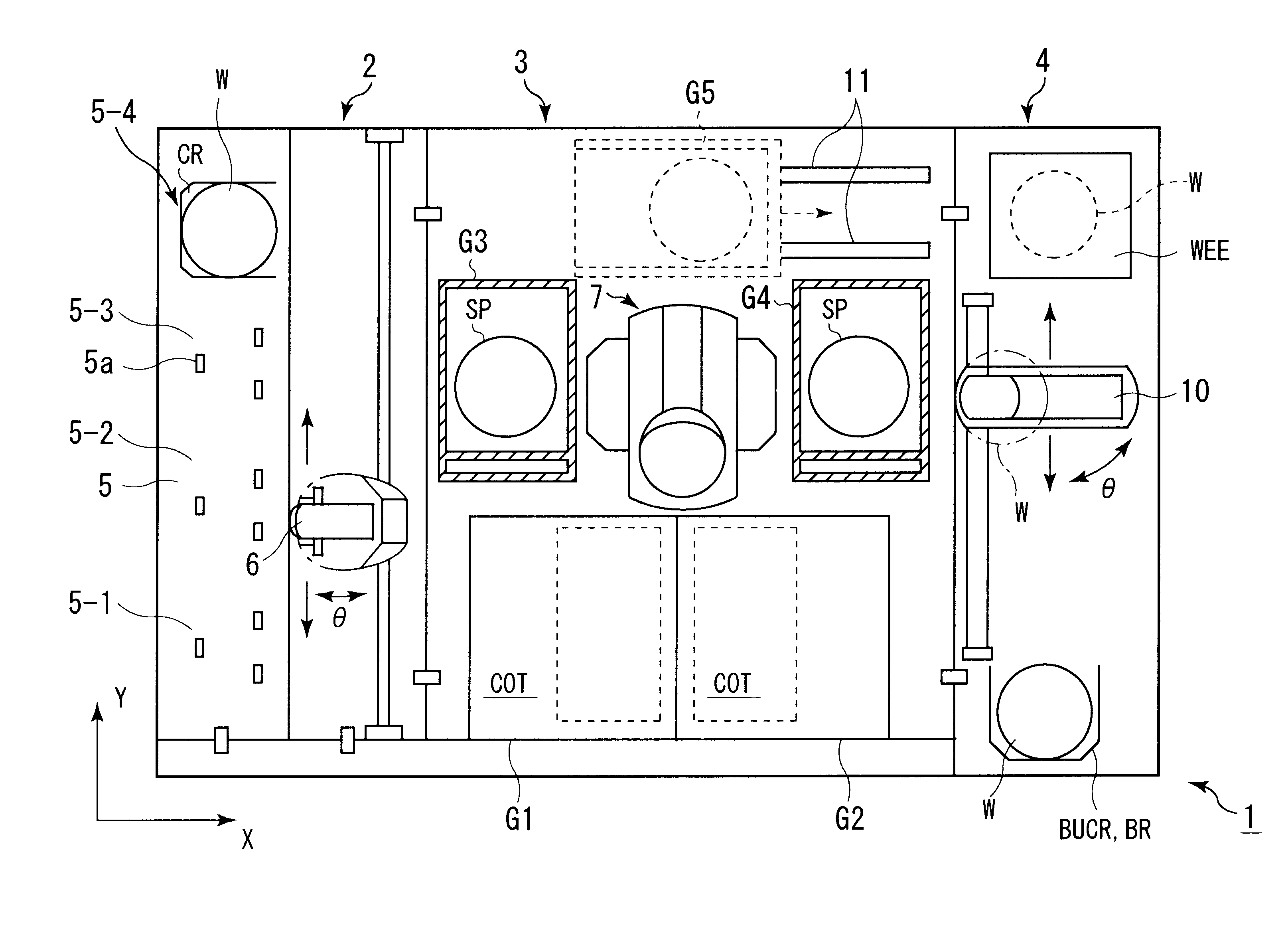
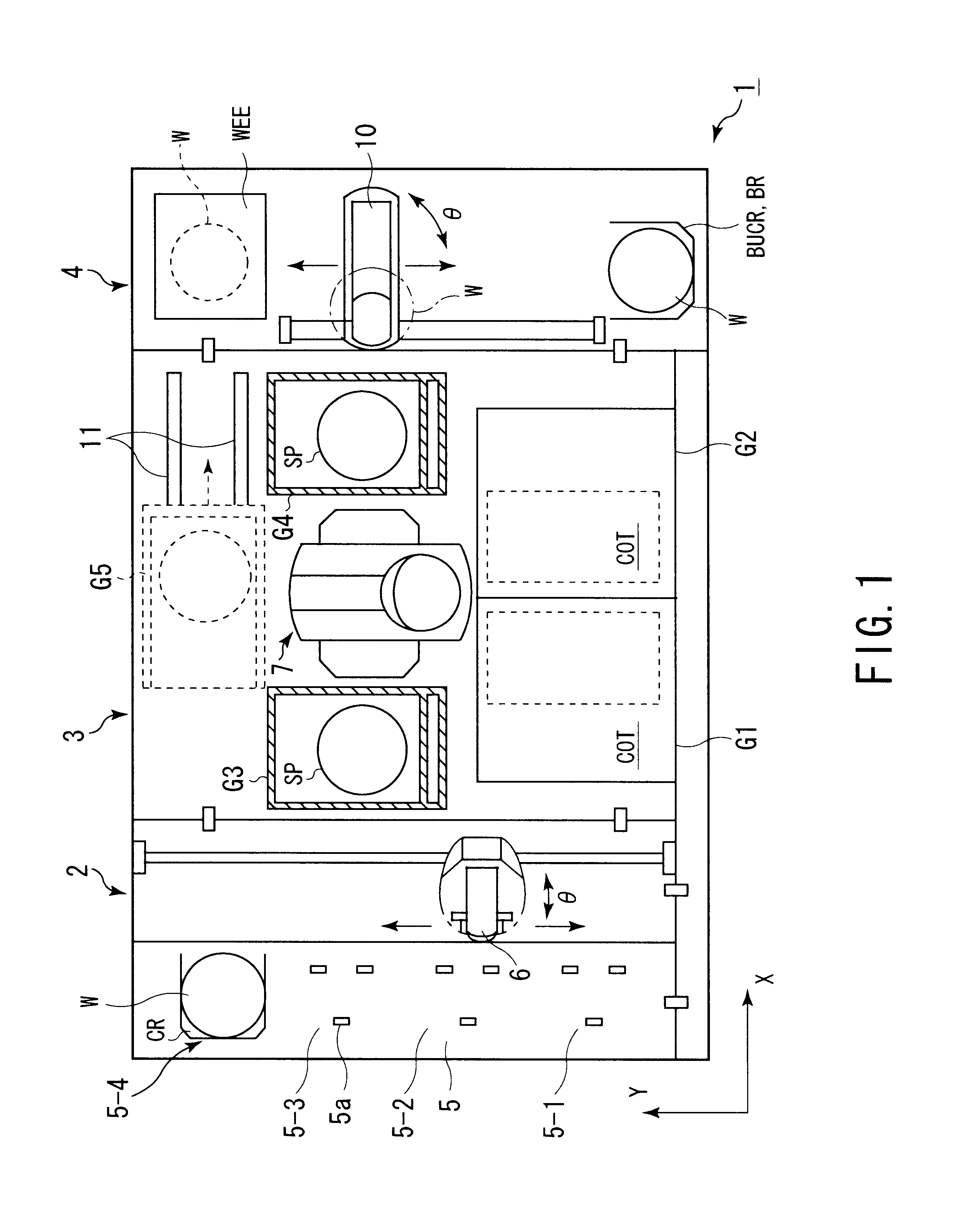
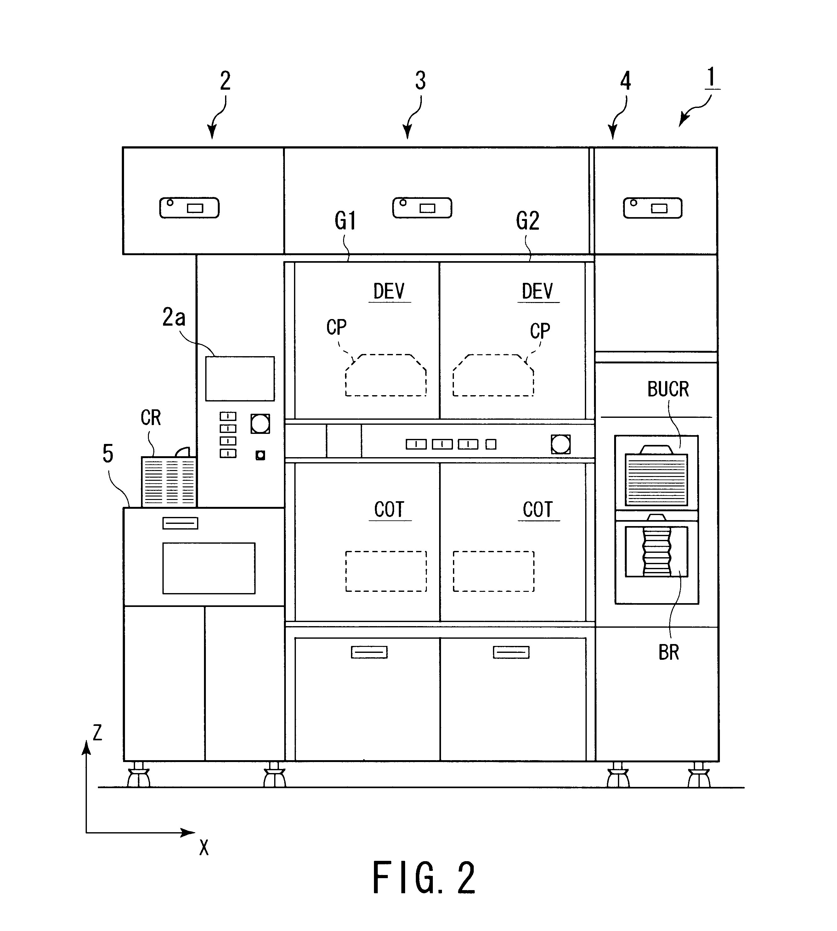
FIGS. 1 to 3 are schematic diagrams showing the overall structure of a substrate processing system 1 according to a first embodiment of the present invention. The substrate processing system 1 comprises a loading / unloading portion 2, a processing portion 3, and an interface portion 4. The loading / unloading portion 2 successively extracts wafers W from a cassette CR. The processing portion 3 performs a resist solution coating process and a developing process for a wafer W extracted from the cassette CR by the loading / unloading portion 2. The interface portion 4 transfers the wafer W that has been coated with a resist solution to an exposing device 12. The interface portion 4 has a second sub-arm mechanism 10. The second sub-arm mechanism 10 exchanges the wafer W with the exposing device 12. The loading / unloading portion 2 has a holding table 5 on which a semiconductor wafer W is extracted and returned from / to a cassette CR.

As shown in FIG. 1, in the loading / unloadin...

second embodiment

(Second Embodiment)

Next, a modification of the first embodiment will be described as a second embodiment of the present invention. According to the second embodiment, when the operator could not change a cassette CR in a time period for which the cassette CR can be changed, the successive lot processes are suspended. According to the second embodiment, in such a case, the heat process start time for each heat processing unit is compensated.

As was described in the first embodiment, the heat process start time has been obtained when the successive lot processes are performed (namely, when real processes for the first lot are performed). However, when the operator could not mistakenly change a cassette CR in the time period for which the cassette CR can be changed, the heat process start time deviates from the real process start time for the first lot. In other words, since a cassette CR has not been changed, the continuous processes for the next lot are not started. However, a heat pr...


PUM


Abstract

A system for successively extracting unprocessed substrates from a cassette, successively conveying the extracted substrates to a plurality of processing units, causing the processing units to process the substrates, and successively returning processed substrates to a cassette is disclosed. In the system, corresponding to a recipe that contains process conditions for each of at least one lot, a process start prediction time at which processes of each lot start and a process completion prediction time at which processes for each lot are completed are calculated for at least two processes. Corresponding to the process start prediction time and the process completion prediction time, at least one of optimum processing units that optimize processes for each lot is selected for each lot.

Description

1. Field of the InventionThe present invention relates to a substrate processing system and a substrate processing method for performing a sequence of processes for various types of substrates such as semiconductor wafers and liquid crystal display (LCD) glass substrates.2. Description of the Related ArtIn fabrication processes for semiconductor devices and LCD glass substrates (LCD substrates), fine circuit patterns are formed using a photolithography technology. In the photolithography technology, a resist is coated in a film shape on the front surface of a raw substrate such as an LCD substrate or a semiconductor wafer and then exposed with a predetermined pattern. After the exposed pattern is developed and etched., a desired circuit pattern is obtained.Recently, as the sizes of semiconductor wafers are becoming large, in the photolithography process, wafers are successively processed. For example, in a complex processing system that performs both of a resist coating process and ...

Claims


Application Information

Patent Timeline
Patent Type & Authority Patents(United States)
IPC IPC(8): G05B19/418H01L21/00H01L21/677H01L21/02H01L21/027
CPCG05B19/41865H01L21/67276G05B2219/31407G05B2219/45031G05B2219/32305Y02P90/02H01L21/00
Inventor TATEYAMA, MASANORIOKUBO, KENICHIOOKURA, JUN
Owner TOKYO ELECTRON LTD
Why Eureka
Try Eureka