Filter, duplexer, and communication device

a technology of duplexer and filter, applied in the direction of resonators, electrical equipment, waveguides, etc., can solve the problems of inescapable power loss due to edge effect, drawback of one microstrip line resonator, and inability to meet the needs of the user,

Inactive Publication Date: 2003-01-21
MURATA MFG CO LTD
View PDF8 Cites 3 Cited by
  • Summary
  • Abstract
  • Description
  • Claims
  • Application Information

AI Technical Summary

Benefits of technology

The present invention, in a first aspect, provides a filter comprising at least three resonators arranged on a substrate, each of which resonators is an aggregate of a plurality of lines each having a spiral shape, in each of which the two ends of at least a portion of the plurality of lines are disposed respectively at substantially the inner and outer periphery portions of the aggregate and are arranged, preferably symmetrically, around a predetermined point of the substrate, and in each of which the plurality of lines are disposed so as not to intersect each other. In this filter, the spiral direction of the spiral lines in at least one resonator is set to be opposite to that of the spiral lines in the other resonators. These features allow an attenuation pole to be arbitrarily formed on the higher frequency side or the lower frequency side of a pass band when using this filter as a band pass filter.
The present invention, in a second aspect, provides a filter comprising at least three resonators arranged on a substrate, in each of which resonators the two ends of a plurality of lines are disposed respectively at substantially the inner and outer periphery portions, arranged preferably symmetrically around a predetermined point of a substrate, and in each of which the plurality of lines are disposed so as not to intersect each other. This filter further comprises input / output portions, and a coupling conductor provided at the inner periphery portion of at least one resonator. The inner periphery portion and the input / output portions are capacitively coupled by the coupling conductor. As in the case of the first aspect, these features allow an attenuation pole to be arbitrarily formed on the higher frequency side or the lower frequency side of a pass band.
The present invention, in a third aspect, provides a duplexer including a filter in accordance with the first or second aspect, usable as a transmitting filter or a receiving filter, or including filters in accordance with the first or second aspect, usable as a transmitting filter and a receiving filter. This makes it possible to provide a predetermined pass band, to reduce the insertion loss, to achieve an overall size-reduction of the filter, and to reliably prevent interference at an adjacent regions between a transmission band and a reception band.
The present invention, in a fourth aspect, provides a duplexer wherein the spiral direction of the spiral lines in the resonators constituting a transmitting filter and the spiral direction of the spiral lines in the resonators constituting a receiving filter are set to be opposite to each other. This feature allows the isolation between the transmitting filter and the receiving filter to be improved.
The present invention, in a fifth aspect, provides a communication device using the above-described filter or duplexer. This makes it possible to achieve an overall size-reduction thereof, to reduce the insertion loss at high-frequency transmission / reception portions, to reliably prevent the interference between adjacent bands, and to improve communication qualities such as the noise characteristics and the transmission speed.

Problems solved by technology

The resonator constituted of one microstrip line has a drawback, in that its characteristics are inevitably deteriorated by the edge effect which the microstrip line intrinsically possesses.
Even if the film-thickness of the line is increased, the problem of the power loss due to the edge effect inescapably occurs, since the edge portions at which the current is concentrated can not be widened by an increase in the film-thickness.

Method used


Image

  • Filter, duplexer, and communication device
  • Filter, duplexer, and communication device
  • Filter, duplexer, and communication device

Examples


first embodiment

First, the configuration of a filter in accordance with the present invention will be described with reference to FIG. 5.

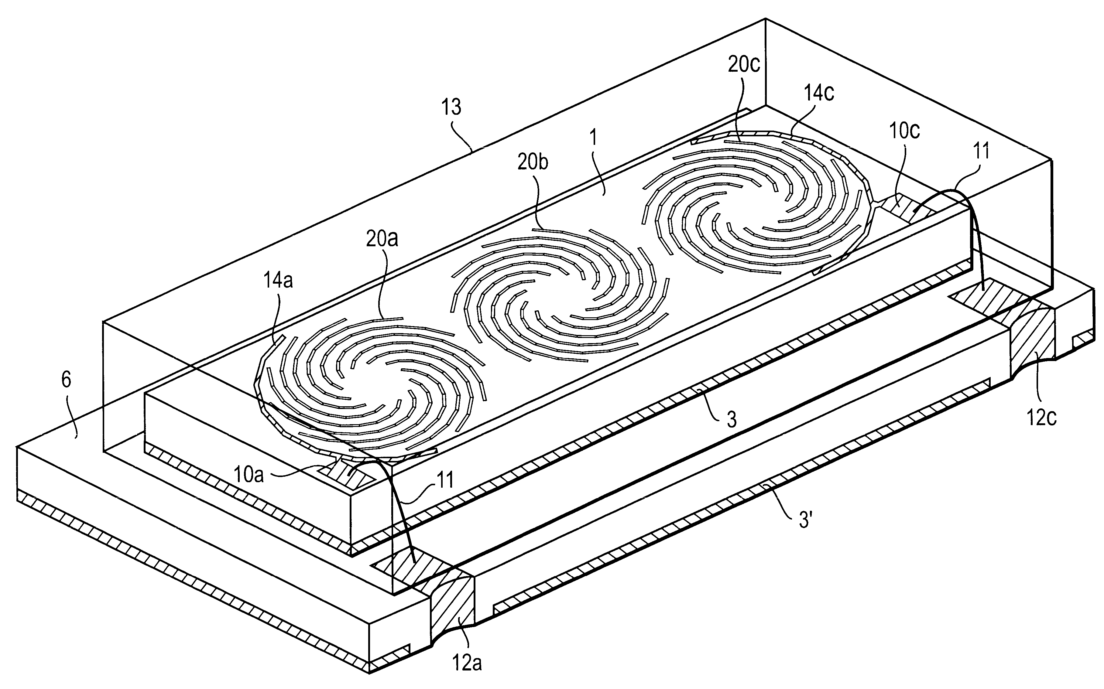
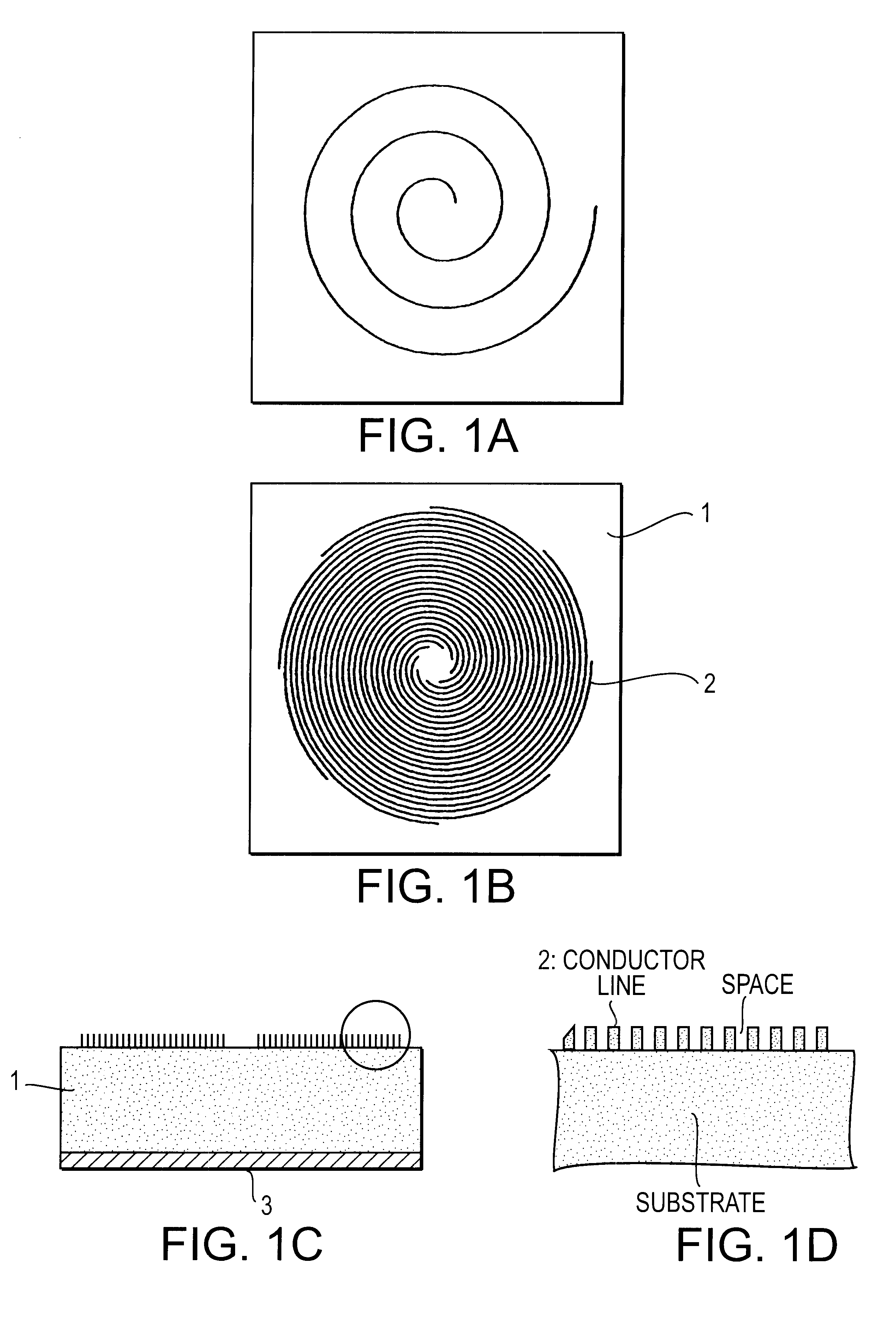
FIG. 5 is a perspective view showing the filter in its entirety. Here, the figure is drawn by seeing through a cap 13. In FIG. 5, reference numeral 1 denotes a high-permittivity substrate formed of LaNbO.sub.3, (Zr, Sn) TiO.sub.4, barium titanate-based material, or the like. By arranging three multiple spiral lines on the top surface of this substrate, three multiple spiral resonators are formed. At the outer periphery portions of the dispositional area of the two outermost multiple spiral lines among these three multiple spiral lines, outer periphery coupling electrodes 14a and 14c which create an electrostatic capacitance between the outer peripheral edges and these electrodes are each formed. On the top surface of the dielectric substrate 1, bonding pads 10a and 10c are also formed. A ground electrode 3 is formed over substantially the entire bottom surface of ...

second embodiment

FIG. 6 is a perspective view showing a filter in accordance with the present invention. In this example, unlike the filter shown in FIG. 5, the first-stage resonator formed of the multiple spiral line 20a and the third-stage resonator formed of the multiple spiral line 20c are each set to be left-handed resonators, and the second-stage resonator formed of the multiple spiral line 20b is set to be a right-handed resonator. As shown in FIG. 15 and others, since the coupling between a left-handed resonator and a right-handed resonator is weaker than that between two left-handed resonators, the coupling between the adjacent resonators in the three stages shown in FIG. 6 is weak, which provides passing characteristics in a narrow bandwidth. In this connection, if all of the three resonators are set to be left-handed resonators, the spacings among these resonators must be increased in order to obtain a narrow pass band, which would result in an overall increase in the size of the filter. ...

fourth embodiment

Next, a filter in accordance with the present invention will be described in reference to FIGS. 8 and 9.

FIG. 8 is a perspective view of this filter. Unlike the example shown in FIG. 7, a ring-shaped connection electrode 8b is connected to the inner peripheral edge of the multiple spiral line of the second-stage resonator. Inside this connection electrode 8b, there is further formed a coupling pad 9 for creating an electrostatic capacitance between the connection electrode 8b and this coupling pad 9. Also, circular connection electrodes 8a and 8c are connected to the inner peripheral edges of the multiple spiral lines of the first-stage and third-stage resonators.

FIG. 9 shows a comparison of the spurious response characteristics of the resonator, when the inner peripheral edges of the multiple spiral resonators are connected by the connection electrodes 8a, 8b and 8c, and when they are not connected. As can be seen from this figure, when the inner peripheral edges of the multiple spi...


PUM

PropertyMeasurementUnit
phase angleaaaaaaaaaa
space widthaaaaaaaaaa

Abstract

A filter and a duplexer in which power loss due to the edge effect in resonator lines, is very effectively suppressed, which allow more reduction in overall size to be achieved, and which have desired filter characteristics, and a communication device including either or both of the filter and the duplexer. Three multiple spiral resonator stages are constructed by disposing three multiple spiral lines on the top surface of a dielectric substrate, and forming a ground electrode on the bottom surface thereof. If the first stage is set to be a right-handed spiral resonator, and the second and third stages are set to be left-handed spiral resonators, an attenuation pole is thereby created on the higher frequency side of a pass band.

Description

1. Field of the InventionThe present invention relates to a filter, a duplexer, and a communication device for use in radio communication or the transmission / reception of electromagnetic waves, in e.g. a microwave band or a millimeter wave band.2. Description of the Related ArtAs an example of a miniaturizable resonator which is used in a microwave band or millimeter wave band, a spiral resonator is disclosed in Japanese Unexamined Patent Application Publication No. 2-96402. This spiral resonator provides a longer resonance line in a given occupied area by forming the resonance line into a spiral shape, thereby achieving an overall size-reduction.In a conventional resonator, one half wavelength line constitutes one resonator. Therefore, in a conventional resonator, the region where electrical energy is concentrated and stored, and the region where magnetic energy is concentrated and stored are separated from each other and unevenly distributed at specific areas of a dielectric subst...

Claims


Application Information

Patent Timeline
Patent Type & Authority Patents(United States)
IPC IPC(8): H01P1/203H01P1/213H01P7/08H01P1/20H01P1/205H04B1/50
CPCH01P1/20381H01P7/082H01P1/2135H01P7/08
Inventor OTA, MICHIAKIHIDAKA, SEIJIFUJII, YASUOABE, SHIN
Owner MURATA MFG CO LTD
Why Eureka
Try Eureka